Ethernet
Overview of Ethernet
Ethernet - Standards and Implementation
IEEE Standards
The first LAN in the world was the original version of Ethernet. Robert Metcalfe and his coworkers at Xerox designed it more than thirty years ago. The first Ethernet standard was published in 1980 by a consortium of Digital Equipment Corporation, Intel, and Xerox (DIX). Metcalfe wanted Ethernet to be a shared standard from which everyone could benefit, and therefore it was released as an open standard. The first products that were developed from the Ethernet standard were sold in the early 1980s. In 1985, the Institute of Electrical and Electronics Engineers (IEEE) standards committee for Local and Metropolitan Networks published standards for LANs. These standards start with the number 802. The standard for Ethernet is 802.3. The IEEE wanted to make sure that its standards were compatible with those of the International Standards Organization (ISO) and OSI model. To ensure compatibility, the IEEE 802.3 standards had to address the needs of Layer 1 and the lower portion of Layer 2 of the OSI model. As a result, some small modifications to the original Ethernet standard were made in 802.3.
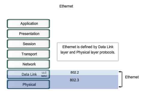
Ethernet operates in the lower two layers of the OSI model: the Data Link layer and the Physical layer.
Ethernet - Layer 1 and Layer 2
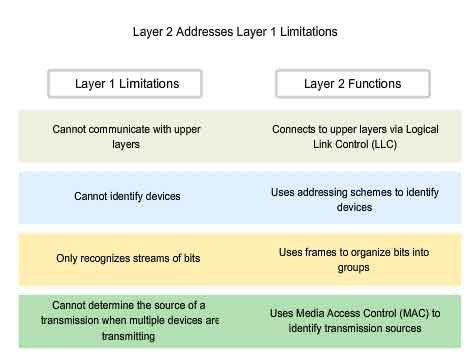
Ethernet operates across two layers of the OSI model. The model provides a reference to which Ethernet can be related but it is actually implemented in the lower half of the Data Link layer, which is known as the Media Access Control (MAC) sublayer, and the Physical layer only. Ethernet at Layer 1 involves signals, bit streams that travel on the media, physical components that put signals on media, and various topologies. Ethernet Layer 1 performs a key role in the communication that takes place between devices, but each of its functions has limitations. As the figure shows, Ethernet at Layer 2 addresses these limitations.
The Data Link sublayers contribute significantly to technological compatibility and computer communications. The MAC sublayer is concerned with the physical components that will be used to communicate the information and prepares the data for transmission over the media.
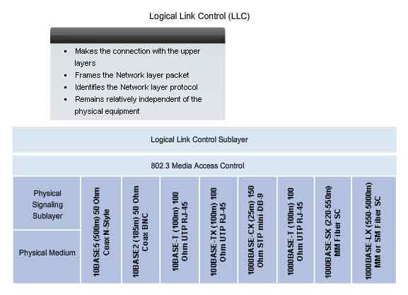
The Logical Link Control (LLC) sublayer remains relatively independent of the physical equipment that will be used for the communication process.
Logical Link Control - Connecting to the Upper Layers
Ethernet separates the functions of the Data Link layer into two distinct sublayers: the Logical Link Control (LLC) sublayer and the Media Access Control (MAC) sublayer. The functions described in the OSI model for the Data Link layer are assigned to the LLC and MAC sublayers. The use of these sublayers contributes significantly to compatibility between diverse end devices. For Ethernet, the IEEE 802.2 standard describes the LLC sublayer functions, and the 802.3 standard describes the MAC sublayer and the Physical layer functions. Logical Link Control handles the communication between the upper layers and the networking software, and the lower layers, typically the hardware. The LLC sublayer takes the network protocol data, which is typically an IPv4 packet, and adds control information to help deliver the packet to the destination node. Layer 2 communicates with the upper layers through LLC. LLC is implemented in software, and its implementation is independent of the physical equipment. In a computer, the LLC can be considered the driver software for the Network Interface Card (NIC). The NIC driver is a program that interacts directly with the hardware on the NIC to pass the data between the media and the Media Access Control sublayer.
http://standards.ieee.org/getieee802/download/802.2-1998.pdf
http://standards.ieee.org/regauth/llc/llctutorial.html
http://www.wildpackets.com/support/compendium/reference/sap_numbers
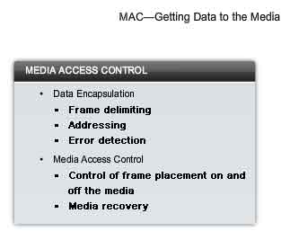
MAC - Getting Data to the Media
Media Access Control (MAC) is the lower Ethernet sublayer of the Data Link layer. Media Access Control is implemented by hardware, typically in the computer Network Interface Card (NIC).
The Ethernet MAC sublayer has two primary responsibilities:
-
Data Encapsulation
- Media Access Control
Data Encapsulation
Data encapsulation provides three primary functions:
-
Frame delimiting
- Addressing
- Error detection
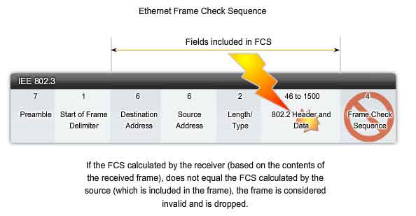
The data encapsulation process includes frame assembly before transmission and frame parsing upon reception of a frame. In forming the frame, the MAC layer adds a header and trailer to the Layer 3 PDU. The use of frames aids in the transmission of bits as they are placed on the media and in the grouping of bits at the receiving node. The framing process provides important delimiters that are used to identify a group of bits that make up a frame. This process provides synchronization between the transmitting and receiving nodes. The encapsulation process also provides for Data Link layer addressing. Each Ethernet header added in the frame contains the physical address (MAC address) that enables a frame to be delivered to a destination node. An additional function of data encapsulation is error detection. Each Ethernet frame contains a trailer with a cyclic redundancy check (CRC) of the frame contents. After reception of a frame, the receiving node creates a CRC to compare to the one in the frame. If these two CRC calculations match, the frame can be trusted to have been received without error.
Media Access Control
The MAC sublayer controls the placement of frames on the media and the removal of frames from the media. As its name implies, it manages the media access control. This includes the initiation of frame transmission and recovery from transmission failure due to collisions.
Logical Topology
The underlying logical topology of Ethernet is a multi-access bus. This means that all the nodes (devices) in that network segment share the medium. This further means that all the nodes in that segment receive all the frames transmitted by any node on that segment. Because all the nodes receive all the frames, each node needs to determine if a frame is to be accepted and processed by that node. This requires examining the addressing in the frame provided by the MAC address. Ethernet provides a method for determining how the nodes share access to the media. The media access control method for classic Ethernet is Carrier Sense Multiple Access with Collision Detection (CSMA/CD). This method is described later in the chapter.
http://standards.ieee.org/regauth/groupmac/tutorial.html
Physical Implementations of Ethernet
Most of the traffic on the Internet originates and ends with Ethernet connections. Since its inception in the 1970s, Ethernet has evolved to meet the increased demand for high-speed LANs. When optical fiber media was introduced, Ethernet adapted to this new technology to take advantage of the superior bandwidth and low error rate that fiber offers. Today, the same protocol that transported data at 3 Mbps can carry data at 10 Gbps.
The success of Ethernet is due to the following factors:
-
Simplicity and ease of maintenance
- Ability to incorporate new technologies
- Reliability
- Low cost of installation and upgrade
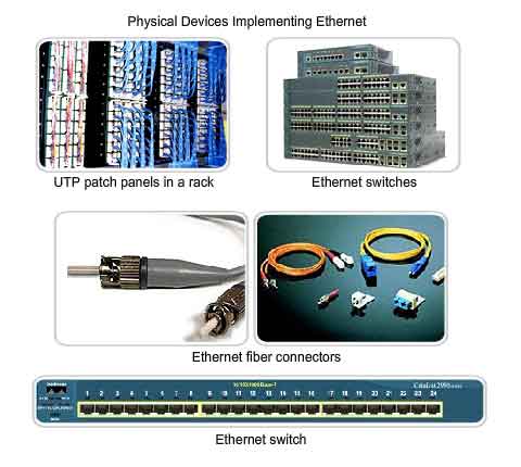
The introduction of Gigabit Ethernet has extended the original LAN technology to distances that make Ethernet a Metropolitan Area Network (MAN) and WAN standard. As a technology associated with the Physical layer, Ethernet specifies and implements encoding and decoding schemes that enable frame bits to be carried as signals across the media. Ethernet devices make use of a broad range of cable and connector specifications. In today's networks, Ethernet uses UTP copper cables and optical fiber to interconnect network devices via intermediary devices such as hubs and switches. With all of the various media types that Ethernet supports , the Ethernet frame structure remains consistent across all of its physical implementations. It is for this reason that it can evolve to meet today's networking requirements.
Ethernet - Communication through the LAN
Historic Ethernet
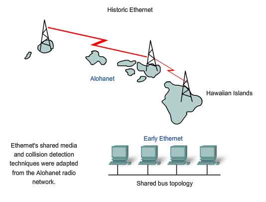
The foundation for Ethernet technology was first established in 1970 with a program called Alohanet. Alohanet was a digital radio network designed to transmit information over a shared radio frequency between the Hawaiian Islands. Alohanet required all stations to follow a protocol in which an unacknowledged transmission required re-transmitting after a short period of waiting. The techniques for using a shared medium in this way were later applied to wired technology in the form of Ethernet. Ethernet was designed to accommodate multiple computers that were Interconnected on a shared bus topology. The first version of Ethernet incorporated a media access method known as Carrier Sense Multiple Access with Collision Detection (CSMA/CD). CSMA/CD managed the problems that result when multiple devices attempt to communicate over a shared physical medium.
Early Ethernet Media
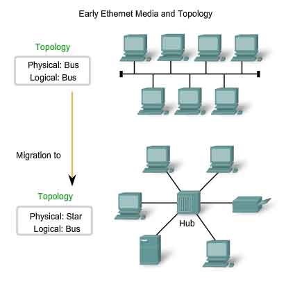
The first versions of Ethernet used coaxial cable to connect computers in a bus topology. Each computer was directly connected to the backbone. These early versions of Ethernet were known as Thicknet, (10BASE5) and Thinnet (10BASE2). 10BASE5, or Thicknet, used a thick coaxial that allowed for cabling distances of up to 500 meters before the signal required a repeater. 10BASE2, or Thinnet, used a thin coaxial cable that was smaller in diameter and more flexible than Thicknet and allowed for cabling distances of 185 meters. The ability to migrate the original implementation of Ethernet to current and future Ethernet implementations is based on the practically unchanged structure of the Layer 2 frame. Physical media, media access, and media control have all evolved and continue to do so. But the Ethernet frame header and trailer have essentially remained constant. The early implementations of Ethernet were deployed in a low-bandwidth LAN environment where access to the shared media was managed by CSMA, and later CSMA/CD. In additional to being a logical bus topology at the Data Link layer, Ethernet also used a physical bus topology. This topology became more problematic as LANs grew larger and LAN services made increasing demands on the infrastructure. The original thick coaxial and thin coaxial physical media were replaced by early categories of UTP cables. Compared to the coaxial cables, the UTP cables were easier to work with, lightweight, and less expensive. The physical topology was also changed to a star topology using hubs. Hubs concentrate connections. In other words, they take a group of nodes and allow the network to see them as a single unit. When a frame arrives at one port, it is copied to the other ports so that all the segments on the LAN receive the frame. Using the hub in this bus topology increased network reliability by allowing any single cable to fail without disrupting the entire network. However, repeating the frame to all other ports did not solve the issue of collisions. Later in this chapter, you will see how issues with collisions in Ethernet networks are managed with the introduction of switches into the network.
Ethernet Collision Management
Legacy Ethernet
In 10BASE-T networks, typically the central point of the network segment was a hub. This created a shared media. Because the media is shared, only one station could successfully transmit at a time. This type of connection is described as a half-duplex communication. As more devices were added to an Ethernet network, the amount of frame collisions increased significantly. During periods of low communications activity, the few collisions that occur are managed by CSMA/CD, with little or no impact on performance. As the number of devices and subsequent data traffic increase, however, the rise in collisions can have a significant impact on the user's experience. A good analogy is when we leave for work or school early in the morning, the roads are relatively clear and not congested. Later when more cars are on the roads, there can be collisions and traffic slows down.
Current Ethernet
A significant development that enhanced LAN performance was the introduction of switches to replace hubs in Ethernet-based networks. This development closely corresponded with the development of 100BASE-TX Ethernet. Switches can control the flow of data by isolating each port and sending a frame only to its proper destination (if the destination is known), rather than send every frame to every device. The switch reduces the number of devices receiving each frame, which in turn reduces or minimizes the possibility of collisions. This, and the later introduction of full-duplex communications (having a connection that can carry both transmitted and received signals at the same time), has enabled the development of 1Gbps Ethernet and beyond.
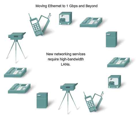
Moving to 1Gbps and Beyond
The applications that cross network links on a daily basis tax even the most robust networks. For example, the increasing use of Voice over IP (VoIP) and multimedia services requires connections that are faster than 100 Mbps Ethernet. Gigabit Ethernet is used to describe Ethernet implementations that provide bandwidth of 1000 Mbps (1 Gbps) or greater. This capacity has been built on the full-duplex capability and the UTP and fiber-optic media technologies of earlier Ethernet. The increase in network performance is significant when potential throughput increases from 100 Mbps to 1 Gbps and above. Upgrading to 1 Gbps Ethernet does not always mean that the existing network infrastructure of cables and switches has to be completely replaced. Some of the equipment and cabling in modern, well-designed and installed networks may be capable of working at the higher speeds with only minimal upgrading. This capability has the benefit of reducing the total cost of ownership of the network.
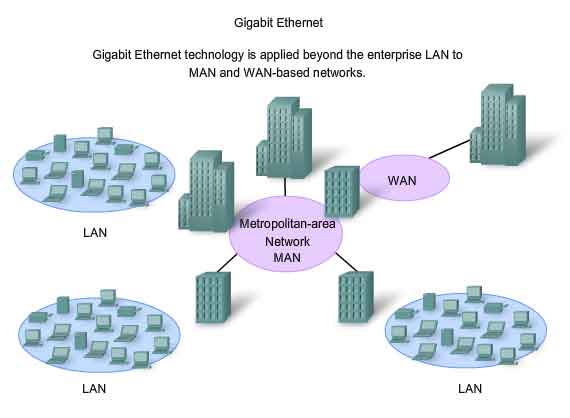
Ethernet Beyond the LAN
The increased cabling distances enabled by the use of fiber-optic cable in Ethernet-based networks has resulted in a blurring of the distinction between LANs and WANs. Ethernet was initially limited to LAN cable systems within single buildings, and then extended to between buildings. It can now be applied across a city in what is known as a Metropolitan Area Network (MAN).
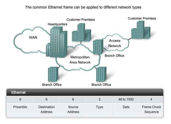
The Ethernet Frame
The Frame - Encapsulating the Packet
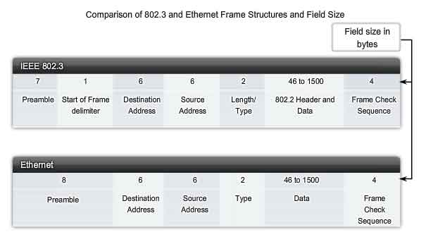
The Ethernet frame structure adds headers and trailers around the Layer 3 PDU to encapsulate the message being sent. Both the Ethernet header and trailer have several sections of information that are used by the Ethernet protocol. Each section of the frame is called a field. There are two styles of Ethernet framing: IEEE 802.3 (original) and the revised IEEE 802.3 (Ethernet). The differences between framing styles are minimal. The most significant difference between the IEEE 802.3 (original) and the revised IEEE 802.3 is the addition of a Start Frame Delimiter (SFD) and a small change to the Type field to include the Length, as shown in the figure.
Ethernet Frame Size
The original Ethernet standard defined the minimum frame size as 64 bytes and the maximum as 1518 bytes. This includes all bytes from the Destination MAC Address field through the Frame Check Sequence (FCS) field. The Preamble and Start Frame Delimiter fields are not included when describing the size of a frame. The IEEE 802.3ac standard, released in 1998, extended the maximum allowable frame size to 1522 bytes. The frame size was increased to accommodate a technology called Virtual Local Area Network (VLAN). VLANs are created within a switched network and will be presented in a later course. If the size of a transmitted frame is less than the minimum or greater than the maximum, the receiving device drops the frame. Dropped frames are likely to be the result of collisions or other unwanted signals and are therefore considered invalid.
Preamble and Start Frame Delimiter Fields
The Preamble (7 bytes) and Start Frame Delimiter (SFD) (1 byte) fields are used for synchronization between the sending and receiving devices. These first eight bytes of the frame are used to get the attention of the receiving nodes. Essentially, the first few bytes tell the receivers to get ready to receive a new frame.
Destination MAC Address Field
The Destination MAC Address field (6 bytes) is the identifier for the intended recipient. As you will recall, this address is used by Layer 2 to assist devices in determining if a frame is addressed to them. The address in the frame is compared to the MAC address in the device. If there is a match, the device accepts the frame.
Source MAC Address Field
The Source MAC Address field (6 bytes) identifies the frame's originating NIC or interface. Switches also use this address to add to their lookup tables. The role of switches will be discussed later in the chapter.
Length/Type Field
The Length/Type field (2 bytes) defines the exact length of the frame's data field. This is used later as part of the FCS to ensure that the message was received properly. Either a length or a type may be entered here. However, only one or the other may be used in a given implementation. If the purpose of the field is to designate a type, the Type field describes which protocol is implemented. The field labeled Length/Type was only listed as Length in the early IEEE versions and only as Type in the DIX version. These two uses of the field were officially combined in a later IEEE version because both uses were common. The Ethernet II Type field is incorporated into the current 802.3 frame definition. Ethernet II is the Ethernet frame format that is used in TCP/IP networks. When a node receives a frame, it must examine the Length/Type field to determine which higher-layer protocol is present. If the two-octet value is equal to or greater than 0x0600 hexadecimal or 1536 decimal, then the contents of the Data Field are decoded according to the protocol indicated.
Data and Pad Fields
The Data and Pad fields (46 - 1500 bytes) contains the encapsulated data from a higher layer, which is a generic Layer 3 PDU, or more commonly, an IPv4 packet. All frames must be at least 64 bytes long. If a small packet is encapsulated, the Pad is used to increase the size of the frame to this minimum size.
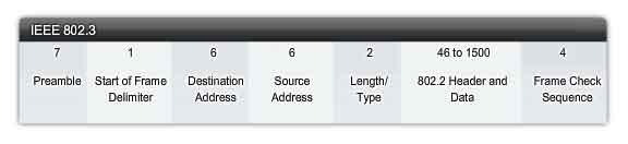
Frame Check Sequence Field
The Frame Check Sequence (FCS) field (4 bytes) is used to detect errors in a frame. It uses a cyclic redundancy check (CRC). The sending device includes the results of a CRC in the FCS field of the frame. The receiving device receives the frame and generates a CRC to look for errors. If the calculations match, no error occurred. Calculations that do not match are an indication that the data has changed; therefore, the frame is dropped. A change in the data could be the result of a disruption of the electrical signals that represent the bits.
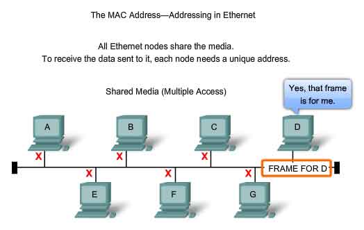
The Ethernet MAC Address
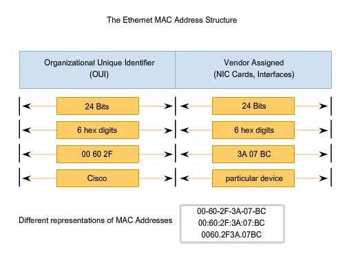
Initially, Ethernet was implemented as part of a bus topology. Every network device was connected to the same, shared media. In low traffic or small networks, this was an acceptable deployment. The main problem to solve was how to identify each device. The signal could be sent to every device, but how would each device identify if it were the intended receiver of the message? A unique identifier called a Media Access Control (MAC) address was created to assist in determining the source and destination address within an Ethernet network. Regardless of which variety of Ethernet was used, the naming convention provided a method for device identification at a lower level of the OSI model. As you will recall, MAC addressing is added as part of a Layer 2 PDU. An Ethernet MAC address is a 48-bit binary value expressed as 12 hexadecimal digits.
MAC Address Structure
The MAC address value is a direct result of IEEE-enforced rules for vendors to ensure globally unique addresses for each Ethernet device. The rules established by IEEE require any vendor that sells Ethernet devices to register with IEEE. The IEEE assigns the vendor a 3-byte code, called the Organizationally Unique Identifier (OUI).
IEEE requires a vendor to follow two simple rules:
-
All MAC addresses assigned to a NIC or other Ethernet device must use that vendor's assigned OUI as the first 3 bytes.
- All MAC addresses with the same OUI must be assigned a unique value (vendor code or serial number) in the last 3 bytes.
The MAC address is often referred to as a burned-in address (BIA) because it is burned into ROM (Read-Only Memory) on the NIC. This means that the address is encoded into the ROM chip permanently - it cannot be changed by software. However, when the computer starts up, the NIC copies the address into RAM. When examining frames, it is the address in RAM that is used as the source address to compare with the destination address. The MAC address is used by the NIC to determine if a message should be passed to the upper layers for processing.
Network Devices
When the source device is forwarding the message to an Ethernet network, the header information within the destination MAC address is attached. The source device sends the data through the network. Each NIC in the network views the information to see if the MAC address matches its physical address. If there is no match, the device discards the frame. When the frame reaches the destination where the MAC of the NIC matches the destination MAC of the frame, the NIC passes the frame up the OSI layers, where the decapsulation process take place. All devices connected to an Ethernet LAN have MAC-addressed interfaces. Different hardware and software manufacturers might represent the MAC address in different hexadecimal formats. The address formats might be similar to 00-05-9A-3C-78-00, 00:05:9A:3C:78:00, or 0005.9A3C.7800. MAC addresses are assigned to workstations, servers, printers, switches, and routers - any device that must originate and/or receive data on the network.
Hexadecimal Numbering and Addressing
Hexadecimal Numbering
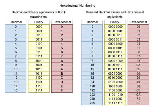
Hexadecimal ("Hex") is a convenient way to represent binary values. Just as decimal is a base ten numbering system and binary is base two, hexadecimal is a base sixteen system. The base 16 numbering system uses the numbers 0 to 9 and the letters A to F. The figure shows the equivalent decimal, binary, and hexadecimal values for binary 0000 to 1111. It is easier for us to express a value as a single hexadecimal digit than as four bits.
Understanding Bytes
Given that 8 bits (a byte) is a common binary grouping, binary 00000000 to 11111111 can be represented in hexadecimal as the range 00 to FF. Leading zeroes are always displayed to complete the 8-bit representation. For example, the binary value 0000 1010 is shown in hexadecimal as 0A.
Representing Hexadecimal Values
Note: It is important to distinguish hexadecimal values from decimal values regarding the characters 0 to 9, as shown in the figure. Hexadecimal is usually represented in text by the value preceded by 0x (for example 0x73) or a subscript 16. Less commonly, it may be followed by an H, for example 73H. However, because subscript text is not recognized in command line or programming environments, the technical representation of hexadecimal is preceded with "0x" (zero X). Therefore, the examples above would be shown as 0x0A and 0x73 respectively. Hexadecimal is used to represent Ethernet MAC addresses and IP Version 6 addresses. You have seen hexadecimal used in the Packets Byte pane of Wireshark where it is used to represent the binary values within frames and packets.
Hexadecimal Conversions
Number conversions between decimal and hexadecimal values are straightforward, but quickly dividing or multiplying by 16 is not always convenient. If such conversions are required, it is usually easier to convert the decimal or hexadecimal value to binary, and then to convert the binary value to either decimal or hexadecimal as appropriate. With practice, it is possible to recognize the binary bit patterns that match the decimal and hexadecimal values. The figure shows these patterns for selected 8-bit values.
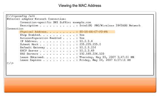
Viewing the MAC
A tool to examine the MAC address of our computer is the ipconfig /all or ifconfig. In the graphic, notice the MAC address of this computer. If you have access, you may wish to try this on your own computer. You may want to research the OUI of the MAC address to determine the manufacturer of your NIC.
Another Layer of Addressing
Data Link Layer
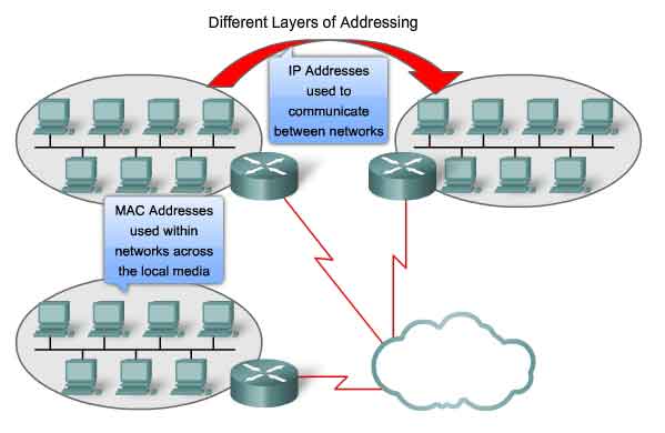
OSI Data Link layer (Layer 2) physical addressing, implemented as an Ethernet MAC address, is used to transport the frame across the local media. Although providing unique host addresses, physical addresses are non-hierarchical. They are associated with a particular device regardless of its location or to which network it is connected. These Layer 2 addresses have no meaning outside the local network media. A packet may have to traverse a number of different Data Link technologies in local and wide area networks before it reaches its destination. A source device therefore has no knowledge of the technology used in intermediate and destination networks or of their Layer 2 addressing and frame structures.
Network Layer
Network layer (Layer 3) addresses, such as IPv4 addresses, provide the ubiquitous, logical addressing that is understood at both source and destination. To arrive at its eventual destination, a packet carries the destination Layer 3 address from its source. However, as it is framed by the different Data Link layer protocols along the way, the Layer 2 address it receives each time applies only to that local portion of the journey and its media.
In short:
-
The Network layer address enables the packet to be forwarded toward its destination.
- The Data Link layer address enables the packet to be carried by the local media across each segment.
Ethernet Unicast, Multicast & Broadcast
In Ethernet, different MAC addresses are used for Layer 2 unicast, multicast, and broadcast communications.
Unicast
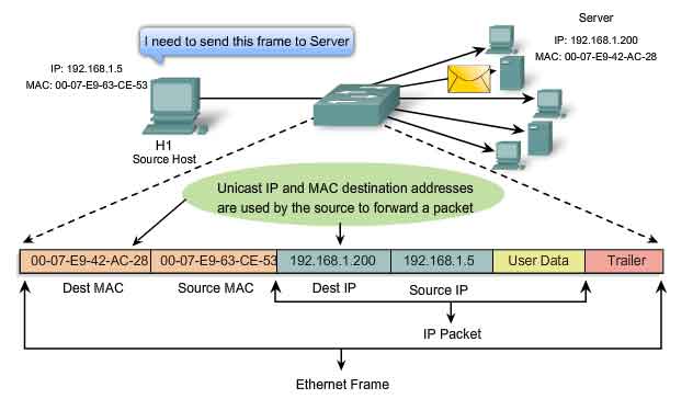
A unicast MAC address is the unique address used when a frame is sent from a single transmitting device to single destination device. In the example shown in the figure, a host with IP address 192.168.1.5 (source) requests a web page from the server at IP address 192.168.1.200. For a unicast packet to be sent and received, a destination IP address must be in the IP packet header. A corresponding destination MAC address must also be present in the Ethernet frame header. The IP address and MAC address combine to deliver data to one specific destination host.
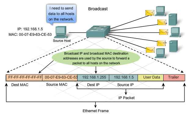
Broadcast
With a broadcast, the packet contains a destination IP address that has all ones (1s) in the host portion. This numbering in the address means that all hosts on that local network (broadcast domain) will receive and process the packet. Many network protocols, such as Dynamic Host Configuration Protocol (DHCP) and Address Resolution Protocol (ARP), use broadcasts. How ARP uses broadcasts to map Layer 2 to Layer 3 addresses is discussed later in this chapter.As shown in the figure, a broadcast IP address for a network needs a corresponding broadcast MAC address in the Ethernet frame. On Ethernet networks, the broadcast MAC address is 48 ones displayed as Hexadecimal FF-FF-FF-FF-FF-FF.
Multicast
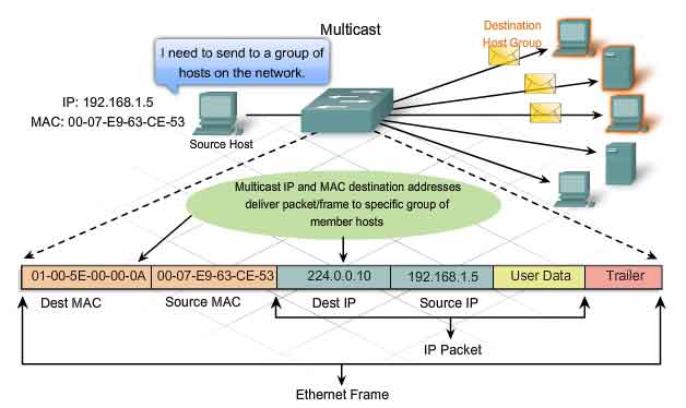
Recall that multicast addresses allow a source device to send a packet to a group of devices. Devices that belong to a multicast group are assigned a multicast group IP address. The range of multicast addresses is from 224.0.0.0 to 239.255.255.255. Because multicast addresses represent a group of addresses (sometimes called a host group), they can only be used as the destination of a packet. The source will always have a unicast address. Examples of where multicast addresses would be used are in remote gaming, where many players are connected remotely but playing the same game, and distance learning through video conferencing, where many students are connected to the same class. As with the unicast and broadcast addresses, the multicast IP address requires a corresponding multicast MAC address to actually deliver frames on a local network. The multicast MAC address is a special value that begins with 01-00-5E in hexadecimal. The value ends by converting the lower 23 bits of the IP multicast group address into the remaining 6 hexadecimal characters of the Ethernet address. The remaining bit in the MAC address is always a "0".
An example, as shown in the graphic, is hexadecimal 01-00-5E-00-00-0A. Each hexadecimal character is 4 binary bits.
http://www.iana.org/assignments/ethernet-numbers
http://www.cisco.com/univercd/cc/td/doc/cisintwk/ito_doc/ipmulti.htm
Ethernet Media Access Control
Media Access Control in Ethernet
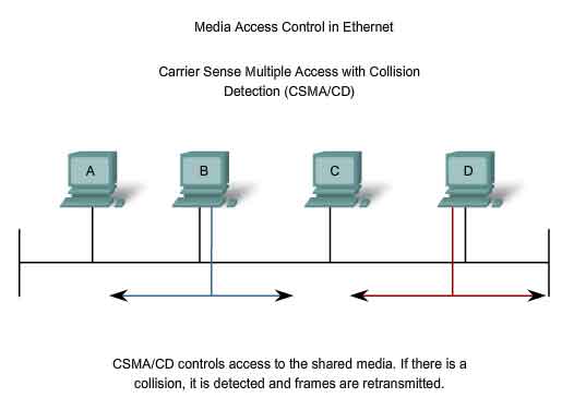
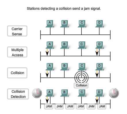
In a shared media environment, all devices have guaranteed access to the medium, but they have no prioritized claim on it. If more than one device transmits simultaneously, the physical signals collide and the network must recover in order for communication to continue. Collisions are the cost that Ethernet pays to get the low overhead associated with each transmission. Ethernet uses Carrier Sense Multiple Access with Collision Detection (CSMA/CD) to detect and handle collisions and manage the resumption of communications. Because all computers using Ethernet send their messages on the same media, a distributed coordination scheme (CSMA) is used to detect the electrical activity on the cable. A device can then determine when it can transmit. When a device detects that no other computer is sending a frame, or carrier signal, the device will transmit, if it has something to send.
CSMA/CD - The Process
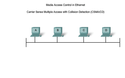
Carrier Sense
In the CSMA/CD access method, all network devices that have messages to send must listen before transmitting. If a device detects a signal from another device, it will wait for a specified amount of time before attempting to transmit. When there is no traffic detected, a device will transmit its message. While this transmission is occurring, the device continues to listen for traffic or collisions on the LAN. After the message is sent, the device returns to its default listening mode.
Multi-access
If the distance between devices is such that the latency of one device's signals means that signals are not detected by a second device, the second device may start to transmit, too. The media now has two devices transmitting their signals at the same time. Their messages will propagate across the media until they encounter each other. At that point, the signals mix and the message is destroyed. Although the messages are corrupted, the jumble of remaining signals continues to propagate across the media.
Collision Detection
When a device is in listening mode, it can detect when a collision occurs on the shared media. The detection of a collision is made possible because all devices can detect an increase in the amplitude of the signal above the normal level. Once a collision occurs, the other devices in listening mode - as well as all the transmitting devices - will detect the increase in the signal amplitude. Once detected, every device transmitting will continue to transmit to ensure that all devices on the network detect the collision.
Jam Signal and Random Backoff
Once the collision is detected by the transmitting devices, they send out a jamming signal. This jamming signal is used to notify the other devices of a collision, so that they will invoke a backoff algorithm. This backoff algorithm causes all devices to stop transmitting for a random amount of time, which allows the collision signals to subside. After the delay has expired on a device, the device goes back into the "listening before transmit" mode. A random backoff period ensures that the devices that were involved in the collision do not try to send their traffic again at the same time, which would cause the whole process to repeat. But, this also means that a third device may transmit before either of the two involved in the original collision have a chance to re-transmit.
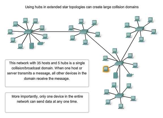
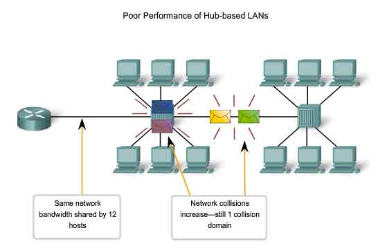
Hubs and Collision Domains
Given that collisions will occur occasionally in any shared media topology - even when employing CSMA/CD - we need to look at the conditions that can result in an increase in collisions. Because of the rapid growth of the Internet:
-
More devices are being connected to the network.
- Devices access the network media more frequently.
- Distances between devices are increasing.
Recall that hubs were created as intermediary network devices that enable more nodes to connect to the shared media. Also known as multi-port repeaters, hubs retransmit received data signals to all connected devices, except the one from which it received the signals. Hubs do not perform network functions such as directing data based on addresses. Hubs and repeaters are intermediary devices that extend the distance that Ethernet cables can reach. Because hubs operate at the Physical layer, dealing only with the signals on the media, collisions can occur between the devices they connect and within the hubs themselves. Further, using hubs to provide network access to more users reduces the performance for each user because the fixed capacity of the media has to be shared between more and more devices. The connected devices that access a common media via a hub or series of directly connected hubs make up what is known as a collision domain. A collision domain is also referred to as a network segment. Hubs and repeaters therefore have the effect of increasing the size of the collision domain. As shown in the figure, the interconnection of hubs form a physical topology called an extended star. The extended star can create a greatly expanded collision domain. An increased number of collisions reduces the network's efficiency and effectiveness until the collisions become a nuisance to the user. Although CSMA/CD is a frame collision management system, it was designed to manage collisions for only limited numbers of devices and on networks with light network usage. Therefore, other mechanisms are required when large numbers of users require access and when more active network access is needed.
We will see that using switches in place of hubs can begin to alleviate this problem.
http://standards.ieee.org/getieee802/802.3.html
Ethernet Timing
Faster Physical layer implementations of Ethernet introduce complexities to the management of collisions.
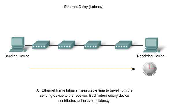
Latency
As discussed, each device that wants to transmit must first "listen" to the media to check for traffic. If no traffic exists, the station will begin to transmit immediately. The electrical signal that is transmitted takes a certain amount of time (latency) to propagate (travel) down the cable. Each hub or repeater in the signal's path adds latency as it forwards the bits from one port to the next. This accumulated delay increases the likelihood that collisions will occur because a listening node may transition into transmitting signals while the hub or repeater is processing the message. Because the signal had not reached this node while it was listening, it thought that the media was available. This condition often results in collisions.
Timing and Synchronization
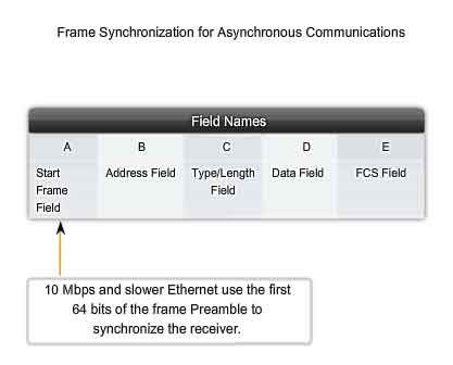
In half-duplex mode, if a collision has not occurred, the sending device will transmit 64 bits of timing synchronization information, which is known as the Preamble. The sending device will then transmit the complete frame. Ethernet with throughput speeds of 10 Mbps and slower are asynchronous. An asynchronous communication in this context means that each receiving device will use the 8 bytes of timing information to synchronize the receive circuit to the incoming data and then discard the 8 bytes. Ethernet implementations with throughput of 100 Mbps and higher are synchronous. Synchronous communication in this context means that the timing information is not required. However, for compatibility reasons, the Preamble and Start Frame Delimiter (SFD) fields are still present.
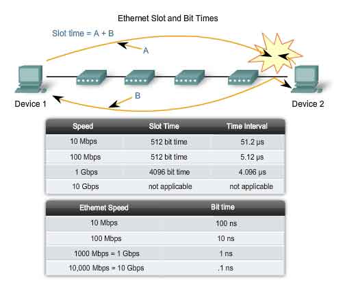
Bit Time
For each different media speed, a period of time is required for a bit to be placed and sensed on the media. This period of time is referred to as the bit time. On 10-Mbps Ethernet, one bit at the MAC layer requires 100 nanoseconds (nS) to transmit. At 100 Mbps, that same bit requires 10 nS to transmit. And at 1000 Mbps, it only takes 1 nS to transmit a bit. As a rough estimate, 20.3 centimeters (8 inches) per nanosecond is often used for calculating the propagation delay on a UTP cable. The result is that for 100 meters of UTP cable, it takes just under 5 bit times for a 10BASE-T signal to travel the length the cable. For CSMA/CD Ethernet to operate, the sending device must become aware of a collision before it has completed transmission of a minimum-sized frame. At 100 Mbps, the device timing is barely able to accommodate 100 meter cables. At 1000 Mbps, special adjustments are required because nearly an entire minimum-sized frame would be transmitted before the first bit reached the end of the first 100 meters of UTP cable. For this reason, half-duplex mode is not permitted in 10-Gigabit Ethernet. These timing considerations have to be applied to the interframe spacing and backoff times (both of which are discussed in the next section) to ensure that when a device transmits its next frame, the risk of a collision is minimized.
Slot Time
In half-duplex Ethernet, where data can only travel in one direction at once, slot time becomes an important parameter in determining how many devices can share a network. For all speeds of Ethernet transmission at or below 1000 Mbps, the standard describes how an individual transmission may be no smaller than the slot time. Determining slot time is a trade-off between the need to reduce the impact of collision recovery (backoff and retransmission times) and the need for network distances to be large enough to accommodate reasonable network sizes. The compromise was to choose a maximum network diameter (about 2500 meters) and then to set the minimum frame length long enough to ensure detection of all worst-case collisions. Slot time for 10- and 100-Mbps Ethernet is 512 bit times, or 64 octets. Slot time for 1000-Mbps Ethernet is 4096 bit times, or 512 octets. The slot time ensures that if a collision is going to occur, it will be detected within the first 512 bits (4096 for Gigabit Ethernet) of the frame transmission. This simplifies the handling of frame retransmissions following a collision.
Slot time is an important parameter for the following reasons:
-
The 512-bit slot time establishes the minimum size of an Ethernet frame as 64 bytes. Any frame less than 64 bytes in length is considered a "collision fragment" or "runt frame" and is automatically discarded by receiving stations.
- The slot time establishes a limit on the maximum size of a network's segments. If the network grows too big, late collisions can occur. Late collisions are considered a failure in the network because the collision is detected too late by a device during the frame transmission to be automatically handled by CSMA/CD.
Slot time is calculated assuming maximum cable lengths on the largest legal network architecture. All hardware propagation delay times are at the legal maximum and the 32-bit jam signal is used when collisions are detected. The actual calculated slot time is just longer than the theoretical amount of time required to travel between the furthest points of the collision domain, collide with another transmission at the last possible instant, and then have the collision fragments return to the sending station and be detected. See the figure. For the system to work properly, the first device must learn about the collision before it finishes sending the smallest legal frame size. To allow 1000 Mbps Ethernet to operate in half-duplex mode, the extension field was added to the frame when sending small frames purely to keep the transmitter busy long enough for a collision fragment to return. This field is present only on 1000-Mbps, half-duplex links and allows minimum-sized frames to be long enough to meet slot time requirements. Extension bits are discarded by the receiving device.
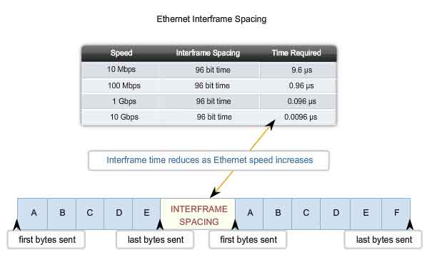
Interframe Spacing and Backoff
Interframe Spacing
The Ethernet standards require a minimum spacing between two non-colliding frames. This gives the media time to stabilize after the transmission of the previous frame and time for the devices to process the frame. Referred to as the interframe spacing, this time is measured from the last bit of the FCS field of one frame to the first bit of the Preamble of the next frame. After a frame has been sent, all devices on a 10 Mbps Ethernet network are required to wait a minimum of 96 bit times (9.6 microseconds) before any device can transmit its next frame. On faster versions of Ethernet, the spacing remains the same - 96 bit times - but the interframe spacing time period grows correspondingly shorter. Synchronization delays between devices may result in the loss of some of frame preamble bits. This in turn may cause minor reduction of the interframe spacing when hubs and repeaters regenerate the full 64 bits of timing information (the Preamble and SFD) at the start of every frame forwarded. On higher speed Ethernet some time sensitive devices could potentially fail to recognize individual frames resulting in communication failure.
Jam Signal
As you will recall, Ethernet allows all devices to compete for transmitting time. In the event that two devices transmit simultaneously, the network CSMA/CD attempts to resolve the issue. But remember, when a larger number of devices are added to the network, it is possible for the collisions to become increasingly difficult to resolve. As soon as a collision is detected, the sending devices transmit a 32-bit "jam" signal that will enforce the collision. This ensures all devices in the LAN to detect the collision. It is important that the jam signal not be detected as a valid frame; otherwise the collision would not be identified. The most commonly observed data pattern for a jam signal is simply a repeating 1, 0, 1, 0 pattern, the same as the Preamble. The corrupted, partially transmitted messages are often referred to as collision fragments or runts. Normal collisions are less than 64 octets in length and therefore fail both the minimum length and the FCS tests, making them easy to identify.
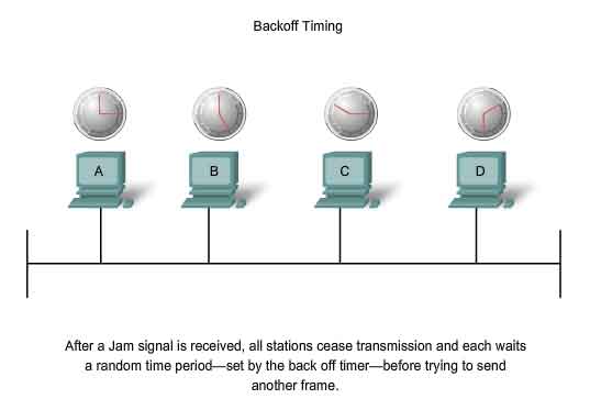
Backoff Timing
After a collision occurs and all devices allow the cable to become idle (each waits the full interframe spacing), the devices whose transmissions collided must wait an additional - and potentially progressively longer - period of time before attempting to retransmit the collided frame. The waiting period is intentionally designed to be random so that two stations do not delay for the same amount of time before retransmitting, which would result in more collisions. This is accomplished in part by expanding the interval from which the random retransmission time is selected on each retransmission attempt. The waiting period is measured in increments of the parameter slot time. If media congestion results in the MAC layer unable to send the frame after 16 attempts, it gives up and generates an error to the Network layer. Such an occurrence is rare in a properly operating network and would happen only under extremely heavy network loads or when a physical problem exists on the network. The methods described in this section allowed Ethernet to provide greater service in a shared media topology based on the use of hubs. In the coming switching section, we will see how, with the use of switches, the need for CSMA/CD starts to diminish or, in some cases, is removed altogether.
Ethernet Physical Layer
Overview of Ethernet Physical Layer
The differences between standard Ethernet, Fast Ethernet, Gigabit Ethernet, and 10 Gigabit Ethernet occur at the Physical layer, often referred to as the Ethernet PHY. Ethernet is covered by the IEEE 802.3 standards. Four data rates are currently defined for operation over optical fiber and twisted-pair cables:
-
10 Mbps - 10Base-T Ethernet
- 100 Mbps - Fast Ethernet
- 1000 Mbps - Gigabit Ethernet
- 10 Gbps - 10 Gigabit Ethernet
While there are many different implementations of Ethernet at these various data rates, only the more common ones will be presented here. The figure shows some of the Ethernet PHY characteristics. The portion of Ethernet that operates on the Physical layer will be discussed in this section, beginning with 10Base-T and continuing to 10 Gbps varieties.
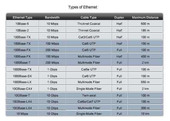
10 and 100 Mbps Ethernet
The principal 10 Mbps implementations of Ethernet include:
-
10BASE5 using Thicknet coaxial cable
- 10BASE2 using Thinnet coaxial cable
- 10BASE-T using Cat3/Cat5 unshielded twisted-pair cable
The early implementations of Ethernet, 10BASE5, and 10BASE2 used coaxial cable in a physical bus. These implementations are no longer used and are not supported by the newer 802.3 standards.
10 Mbps Ethernet - 10BASE-T
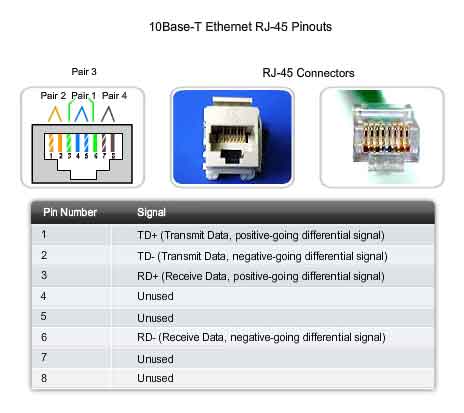
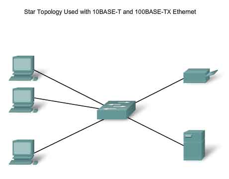
10BASE-T uses Manchester-encoding over two unshielded twisted-pair cables. The early implementations of 10BASE-T used Cat3 cabling. However, Cat5 or later cabling is typically used today. 10 Mbps Ethernet is considered to be classic Ethernet and uses a physical star topology. Ethernet 10BASE-T links could be up to 100 meters in length before requiring a hub or repeater. 10BASE-T uses two pairs of a four-pair cable and is terminated at each end with an 8-pin RJ-45 connector. The pair connected to pins 1 and 2 are used for transmitting and the pair connected to pins 3 and 6 are used for receiving. The figure shows the RJ45 pinout used with 10BASE-T Ethernet. 10BASE-T is generally not chosen for new LAN installations. However, there are still many 10BASE-T Ethernet networks in existence today. The replacement of hubs with switches in 10BASE-T networks has greatly increased the throughput available to these networks and has given Legacy Ethernet greater longevity. The 10BASE-T links connected to a switch can support either half-duplex or full-duplex operation.
100 Mbps - Fast Ethernet
In the mid to late 1990s, several new 802.3 standards were established to describe methods for transmitting data over Ethernet media at 100 Mbps. These standards used different encoding requirements for achieving these higher data rates. 100 Mbps Ethernet, also known as Fast Ethernet, can be implemented using twisted-pair copper wire or fiber media. The most popular implementations of 100 Mbps Ethernet are:
-
100BASE-TX using Cat5 or later UTP
- 100BASE-FX using fiber-optic cable
Because the higher frequency signals used in Fast Ethernet are more susceptible to noise, two separate encoding steps are used by 100-Mbps Ethernet to enhance signal integrity.
100BASE-TX
100BASE-TX was designed to support transmission over either two pairs of Category 5 UTP copper wire or two strands of optical fiber. The 100BASE-TX implementation uses the same two pairs and pinouts of UTP as 10BASE-T. However, 100BASE-TX requires Category 5 or later UTP. The 4B/5B encoding is used for 100BASE-T Ethernet. As with 10BASE-TX, 100Base-TX is connected as a physical star. The figure shows an example of a physical star topology. However, unlike 10BASE-T, 100BASE-TX networks typically use a switch at the center of the star instead of a hub. At about the same time that 100BASE-TX technologies became mainstream, LAN switches were also being widely deployed. These concurrent developments led to their natural combination in the design of 100BASE-TX networks.
100BASE-FX
The 100BASE-FX standard uses the same signaling procedure as 100BASE-TX, but over optical fiber media rather than UTP copper. Although the encoding, decoding, and clock recovery procedures are the same for both media, the signal transmission is different - electrical pulses in copper and light pulses in optical fiber. 100BASE-FX uses Low Cost Fiber Interface Connectors (commonly called the duplex SC connector). Fiber implementations are point-to-point connections, that is, they are used to interconnect two devices. These connections may be between two computers, between a computer and a switch, or between two switches.
1000 Mbps Ethernet
1000 Mbps - Gigabit Ethernet
The development of Gigabit Ethernet standards resulted in specifications for UTP copper, single-mode fiber, and multimode fiber. On Gigabit Ethernet networks, bits occur in a fraction of the time that they take on 100 Mbps networks and 10 Mbps networks. With signals occurring in less time, the bits become more susceptible to noise, and therefore timing is critical. The question of performance is based on how fast the network adapter or interface can change voltage levels and how well that voltage change can be detected reliably 100 meters away, at the receiving NIC or interface. At these higher speeds, encoding and decoding data is more complex. Gigabit Ethernet uses two separate encoding steps. Data transmission is more efficient when codes are used to represent the binary bit stream. Encoding the data enables synchronization, efficient usage of bandwidth, and improved signal-to-noise ratio characteristics.
1000BASE-T Ethernet
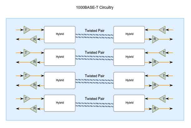
1000BASE-T Ethernet provides full-duplex transmission using all four pairs in Category 5 or later UTP cable. Gigabit Ethernet over copper wire enables an increase from 100 Mbps per wire pair to 125 Mbps per wire pair, or 500 Mbps for the four pairs. Each wire pair signals in full duplex, doubling the 500 Mbps to 1000 Mbps. 1000BASE-T uses 4D-PAM5 line encoding to obtain 1 Gbps data throughput. This encoding scheme enables the transmission signals over four wire pairs simultaneously. It translates an 8-bit byte of data into a simultaneous transmission of four code symbols (4D), which are sent over the media, one on each pair, as 5-level Pulse Amplitude Modulated (PAM5) signals. This means that every symbol corresponds to two bits of data. Because the information travels simultaneously across the four paths, the circuitry has to divide frames at the transmitter and reassemble them at the receiver. The figure shows a representation of the circuitry used by 1000BASE-T Ethernet. 1000BASE-T allows the transmission and reception of data in both directions - on the same wire and at the same time. This traffic flow creates permanent collisions on the wire pairs. These collisions result in complex voltage patterns. The hybrid circuits detecting the signals use sophisticated techniques such as echo cancellation, Layer 1 Forward Error Correction (FEC), and prudent selection of voltage levels. Using these techniques, the system achieves the 1-Gigabit throughput. To help with synchronization, the Physical layer encapsulates each frame with start-of-stream and end-of-stream delimiters. Loop timing is maintained by continuous streams of IDLE symbols sent on each wire pair during the interframe spacing. Unlike most digital signals where there are usually a couple of discrete voltage levels, 1000BASE-T uses many voltage levels. In idle periods, nine voltage levels are found on the cable. During data transmission periods, up to 17 voltage levels are found on the cable. With this large number of states, combined with the effects of noise, the signal on the wire looks more analog than digital. Like analog, the system is more susceptible to noise due to cable and termination problems.
1000BASE-SX and 1000BASE-LX Ethernet Using Fiber-Optics
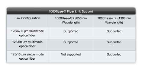
The fiber versions of Gigabit Ethernet - 1000BASE-SX and 1000BASE-LX - offer the following advantages over UTP: noise immunity, small physical size, and increased unrepeated distances and bandwidth. All 1000BASE-SX and 1000BASE-LX versions support full-duplex binary transmission at 1250 Mbps over two strands of optical fiber. The transmission coding is based on the 8B/10B encoding scheme. Because of the overhead of this encoding, the data transfer rate is still 1000 Mbps. Each data frame is encapsulated at the Physical layer before transmission, and link synchronization is maintained by sending a continuous stream of IDLE code groups during the interframe spacing. The principal differences among the 1000BASE-SX and 1000BASE-LX fiber versions are the link media, connectors, and wavelength of the optical signal. These differences are shown in the figure.
Ethernet - Future Options
The IEEE 802.3ae standard was adapted to include 10 Gbps, full-duplex transmission over fiber-optic cable. The 802.3ae standard and the 802.3 standards for the original Ethernet are very similar. 10-Gigabit Ethernet (10GbE) is evolving for use not only in LANs, but also for use in WANs and MANs. Because the frame format and other Ethernet Layer 2 specifications are compatible with previous standards, 10GbE can provide increased bandwidth to individual networks that is interoperable with the existing network infrastructure.
10Gbps can be compared to other varieties of Ethernet in these ways:
-
Frame format is the same, allowing interoperability between all varieties of legacy, fast, gigabit, and 10 gigabit Ethernet, with no reframing or protocol conversions necessary.
- Bit time is now 0.1 ns. All other time variables scale accordingly.
- Because only full-duplex fiber connections are used, there is no media contention and CSMA/CD is not necessary.
- The IEEE 802.3 sublayers within OSI Layers 1 and 2 are mostly preserved, with a few additions to accommodate 40 km fiber links and interoperability with other fiber technologies.
With 10Gbps Ethernet, flexible, efficient, reliable, relatively low cost end-to-end Ethernet networks become possible.
Future Ethernet Speeds
Although 1-Gigabit Ethernet is now widely available and 10-Gigabit products are becoming more available, the IEEE and the 10-Gigabit Ethernet Alliance are working on 40-, 100-, or even 160-Gbps standards. The technologies that are adopted will depend on a number of factors, including the rate of maturation of the technologies and standards, the rate of adoption in the market, and the cost of emerging products.
Hubs and Switches
Legacy Ethernet - Using Hubs
In previous sections, we have seen how classic Ethernet uses shared media and contention-based media access control. Classic Ethernet uses hubs to interconnect nodes on the LAN segment. Hubs do not perform any type of traffic filtering. Instead, the hub forwards all the bits to every device connected to the hub. This forces all the devices in the LAN to share the bandwidth of the media. Additionally, this classic Ethernet implementation often results in high levels of collisions on the LAN. Because of these performance issues, this type of Ethernet LAN has limited use in today's networks. Ethernet implementations using hubs are now typically used only in small LANs or in LANs with low bandwidth requirements. Sharing media among devices creates significant issues as the network grows. The figure illustrates some of the issues presented here.
Scalability
In a hub network, there is a limit to the amount of bandwidth that devices can share. With each device added to the shared media, the average bandwidth available to each device decreases. With each increase in the number of devices on the media, performance is degraded.
Latency
Network latency is the amount of time it takes a signal to reach all destinations on the media. Each node in a hub-based network has to wait for an opportunity to transmit in order to avoid collisions. Latency can increase significantly as the distance between nodes is extended. Latency is also affected by a delay of the signal across the media as well as the delay added by the processing of the signals through hubs and repeaters. Increasing the length of media or the number of hubs and repeaters connected to a segment results in increased latency. With greater latency, it is more likely that nodes will not receive initial signals, thereby increasing the collisions present in the network.
Network Failure
Because classic Ethernet shares the media, any device in the network could potentially cause problems for other devices. If any device connected to the hub generates detrimental traffic, the communication for all devices on the media could be impeded. This harmful traffic could be due to incorrect speed or full-duplex settings on a NIC.
Collisions
According to CSMA/CD, a node should not send a packet unless the network is clear of traffic. If two nodes send packets at the same time, a collision occurs and the packets are lost. Then both nodes send a jam signal, wait for a random amount of time, and retransmit their packets. Any part of the network where packets from two or more nodes can interfere with each other is considered a collision domain. A network with a larger number of nodes on the same segment has a larger collision domain and typically has more traffic. As the amount of traffic in the network increases, the likelihood of collisions increases. Switches provide an alternative to the contention-based environment of classic Ethernet.
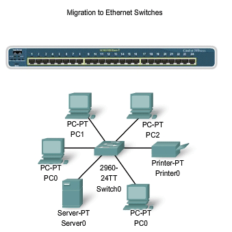
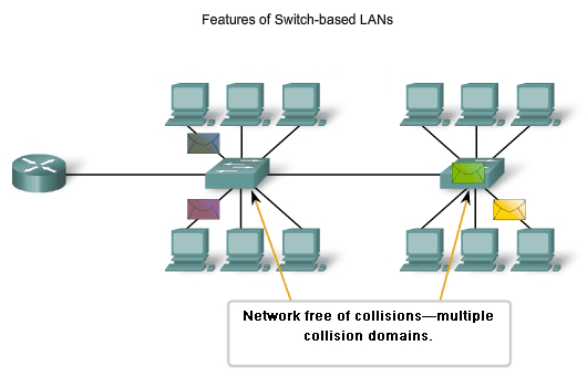
Ethernet - Using Switches
In the last few years, switches have quickly become a fundamental part of most networks. Switches allow the segmentation of the LAN into separate collision domains. Each port of the switch represents a separate collision domain and provides the full media bandwidth to the node or nodes connected on that port. With fewer nodes in each collision domain, there is an increase in the average bandwidth available to each node, and collisions are reduced. A LAN may have a centralized switch connecting to hubs that still provide the connectivity to nodes. Or, a LAN may have all nodes connected directly to a switch. Theses topologies are shown in the figure. In a LAN where a hub is connected to a switch port, there is still shared bandwidth, which may result in collisions within the shared environment of the hub. However, the switch will isolate the segment and limit collisions to traffic between the hub's ports.
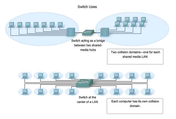
Nodes are Connected Directly
In a LAN where all nodes are connected directly to the switch, the throughput of the network increases dramatically. The three primary reasons for this increase are:
-
Dedicated bandwidth to each port
- Collision-free environment
- Full-duplex operation
These physical star topologies are essentially point to point links.
Dedicated Bandwidth
Each node has the full media bandwidth available in the connection between the node and the switch. Because a hub replicates the signals it receives and sends them to all other ports, classic Ethernet hubs form a logical bus. This means that all the nodes have to share the same bandwidth of this bus. With switches, each device effectively has a dedicated point-to-point connection between the device and the switch, without media contention. As an example, compare two 100 Mbps LANs, each with 10 nodes. In network segment A, the 10 nodes are connected to a hub. Each node shares the available 100 Mbps bandwidth. This provides an average of 10 Mbps to each node. In network segment B, the 10 nodes are connected to a switch. In this segment, all 10 nodes have the full 100 Mbps bandwidth available to them. Even in this small network example, the increase in bandwidth is significant. As the number of nodes increases, the discrepancy between the available bandwidth in the two implementations increases significantly.
Collision-Free Environment
A dedicated point-to-point connection to a switch also removes any media contention between devices, allowing a node to operate with few or no collisions. In a moderately-sized classic Ethernet network using hubs, approximately 40% to 50% of the bandwidth is consumed by collision recovery. In a switched Ethernet network - where there are virtually no collisions - the overhead devoted to collision recovery is virtually eliminated. This provides the switched network with significantly better throughput rates.
Full-Duplex Operation
Switching also allows a network to operate as a full-duplex Ethernet environment. Before switching existed, Ethernet was half-duplex only. This meant that at any given time, a node could either transmit or receive. With full-duplex enabled in a switched Ethernet network, the devices connected directly to the switch ports can transmit and receive simultaneously, at the full media bandwidth. The connection between the device and the switch is collision-free. This arrangement effectively doubles the transmission rate when compared to half-duplex. For example, if the speed of the network is 100 Mbps, each node can transmit a frame at 100 Mbps and, at the same time, receive a frame at 100 Mbps.
Using Switches Instead of Hubs
Most modern Ethernet use switches to the end devices and operate full duplex. Because switches provide so much greater throughput than hubs and increase performance so dramatically, it is fair to ask: why not use switches in every Ethernet LAN? There are three reasons why hubs are still being used:
-
Availability - LAN switches were not developed until the early 1990s and were not readily available until the mid 1990s. Early Ethernet networks used UTP hubs and many of them remain in operation to this day.
- Economics - Initially, switches were rather expensive. As the price of switches has dropped, the use of hubs has decreased and cost is becoming less of a factor in deployment decisions.
- Requirements - The early LAN networks were simple networks designed to exchange files and share printers. For many locations, the early networks have evolved into the converged networks of today, resulting in a substantial need for increased bandwidth available to individual users. In some circumstances, however, a shared media hub will still suffice and these products remain on the market.
The next section explores the basic operation of switches and how a switch achieves the enhanced performance upon which our networks now depend. A later course will present more details and additional technologies related to switching.
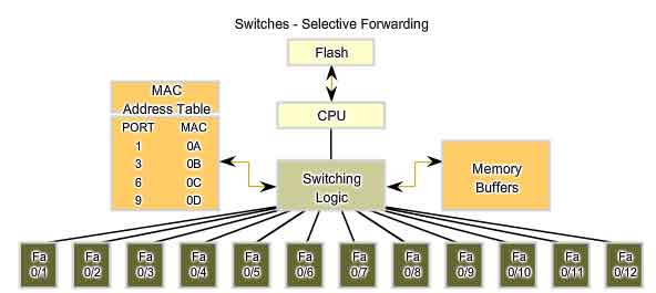
Switches - Selective Forwarding
Ethernet switches selectively forward individual frames from a receiving port to the port where the destination node is connected. This selective forwarding process can be thought of as establishing a momentary point-to-point connection between the transmitting and receiving nodes. The connection is made only long enough to forward a single frame. During this instant, the two nodes have a full bandwidth connection between them and represent a logical point-to-point connection. To be technically accurate, this temporary connection is not made between the two nodes simultaneously. In essence, this makes the connection between hosts a point-to-point connection. In fact, any node operating in full-duplex mode can transmit anytime it has a frame, without regard to the availability of the receiving node. This is because a LAN switch will buffer an incoming frame and then forward it to the proper port when that port is idle. This process is referred to as store and forward. With store and forward switching, the switch receives the entire frame, checks the FSC for errors, and forwards the frame to the appropriate port for the destination node. Because the nodes do not have to wait for the media to be idle, the nodes can send and receive at full media speed without losses due to collisions or the overhead associated with managing collisions.
Forwarding is Based on the Destination MAC
The switch maintains a table, called a MAC table. that matches a destination MAC address with the port used to connect to a node. For each incoming frame, the destination MAC address in the frame header is compared to the list of addresses in the MAC table. If a match is found, the port number in the table that is paired with the MAC address is used as the exit port for the frame. The MAC table can be referred to by many different names. It is often called the switch table. Because switching was derived from an older technology called transparent bridging, the table is sometimes called the bridge table. For this reason, many processes performed by LAN switches can contain bridge or bridging in their names. A bridge is a device used more commonly in the early days of LAN to connect - or bridge - two physical network segments. Switches can be used to perform this operation as well as allowing end device connectivity to the LAN. Many other technologies have been developed around LAN switching. One place where bridges are prevalent is in Wireless networks. We use Wireless Bridges to interconnect two wireless network segments. Therefore, you may find both terms - switching and bridging - in use by the networking industry.
Switch Operation
To accomplish their purpose, Ethernet LAN switches use five basic operations:
-
Learning
- Aging
- Flooding
- Selective Forwarding
- Filtering
Learning
The MAC table must be populated with MAC addresses and their corresponding ports. The Learning process allows these mappings to be dynamically acquired during normal operation. As each frame enters the switch, the switch examines the source MAC address. Using a lookup procedure, the switch determines if the table already contains an entry for that MAC address. If no entry exists, the switch creates a new entry in the MAC table using the source MAC address and pairs the address with the port on which the entry arrived. The switch now can use this mapping to forward frames to this node.
Aging
The entries in the MAC table acquired by the Learning process are time stamped. This timestamp is used as a means for removing old entries in the MAC table. After an entry in the MAC table is made, a procedure begins a countdown, using the timestamp as the beginning value. After the value reaches 0, the entry in the table will be refreshed when the switch next receives a frame from that node on the same port.
Flooding
If the switch does not know to which port to send a frame because the destination MAC address is not in the MAC table, the switch sends the frame to all ports except the port on which the frame arrived. The process of sending a frame to all segments is known as flooding. The switch does not forward the frame to the port on which it arrived because any destination on that segment will have already received the frame. Flooding is also used for frames sent to the broadcast MAC address.
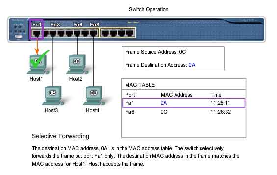
Selective Forwarding
Selective forwarding is the process of examining a frame's destination MAC address and forwarding it out the appropriate port. This is the central function of the switch. When a frame from a node arrives at the switch for which the switch has already learned the MAC address, this address is matched to an entry in the MAC table and the frame is forwarded to the corresponding port. Instead of flooding the frame to all ports, the switch sends the frame to the destination node via its nominated port. This action is called forwarding.
Filtering
In some cases, a frame is not forwarded. This process is called frame filtering. One use of filtering has already been described: a switch does not forward a frame to the same port on which it arrived. A switch will also drop a corrupt frame. If a frame fails a CRC check, the frame is dropped. An additional reason for filtering a frame is security. A switch has security settings for blocking frames to and/or from selective MAC addresses or specific ports.
Address Resolution Protocol (ARP)
The ARP Process - Mapping IP to MAC Addresses
The ARP protocol provides two basic functions:
-
Resolving IPv4 addresses to MAC addresses
- Maintaining a cache of mappings
Resolving IPv4 Addresses to MAC Addresses
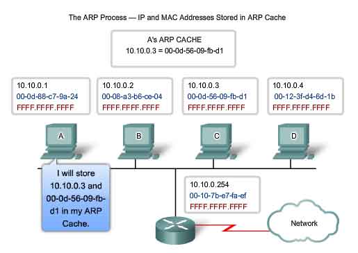
For a frame to be placed on the LAN media, it must have a destination MAC address. When a packet is sent to the Data Link layer to be encapsulated into a frame, the node refers to a table in its memory to find the Data Link layer address that is mapped to the destination IPv4 address. This table is called the ARP table or the ARP cache. The ARP table is stored in the RAM of the device. Each entry, or row, of the ARP table has a pair of values: an IP Address and a MAC address. We call the relationship between the two values a map - it simply means that you can locate an IP address in the table and discover the corresponding MAC address. The ARP table caches the mapping for the devices on the local LAN. To begin the process, a transmitting node attempts to locate in the ARP table the MAC address mapped to an IPv4 destination. If this map is cached in the table, the node uses the MAC address as the destination MAC in the frame that encapsulates the IPv4 packet. The frame is then encoded onto the networking media.
Maintaining the ARP Table
The ARP table is maintained dynamically. There are two ways that a device can gather MAC addresses. One way is to monitor the traffic that occurs on the local network segment. As a node receives frames from the media, it can record the source IP and MAC address as a mapping in the ARP table. As frames are transmitted on the network, the device populates the ARP table with address pairs. Another way a device can get an address pair is to broadcast an ARP request. ARP sends a Layer 2 broadcast to all devices on the Ethernet LAN. The frame contains an ARP request packet with the IP address of the destination host. The node receiving the frame that identifies the IP address as its own responds by sending an ARP reply packet back to the sender as a unicast frame. This response is then used to make a new entry in the ARP table. These dynamic entries in the MAC table are timestamped in much the same way that MAC table entries are timestamped in switches. If a device does not receive a frame from a particular device by the time the timestamp expires, the entry for this device is removed from the ARP table. Additionally, static map entries can be entered in an ARP table, but this is rarely done. Static ARP table entries do expire over time and must be manually removed.
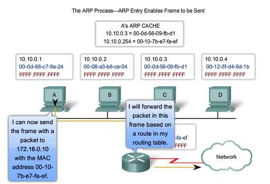
Creating the Frame
What does a node do when it needs to create a frame and the ARP cache does not contain a map of an IP address to a destination MAC address? When ARP receives a request to map an IPv4 address to a MAC address, it looks for the cached map in its ARP table. If an entry is not found, the encapsulation of the IPv4 packet fails and the Layer 2 processes notify ARP that it needs a map. The ARP processes then send out an ARP request packet to discover the MAC address of the destination device on the local network. If a device receiving the request has the destination IP address, it responds with an ARP reply. A map is created in the ARP table. Packets for that IPv4 address can now be encapsulated in frames. If no device responds to the ARP request, the packet is dropped because a frame cannot be created. This encapsulation failure is reported to the upper layers of the device. If the device is an intermediary device, like a router, the upper layers may choose to respond to the source host with an error in an ICMPv4 packet. Click the step numbers in the figure to see the process used to get the MAC address of node on the local physical network.
The ARP Process - Destinations outside the Local Network
All frames must be delivered to a node on the local network segment. If the destination IPv4 host is on the local network, the frame will use the MAC address of this device as the destination MAC address. If the destination IPv4 host is not on the local network, the source node needs to deliver the frame to the router interface that is the gateway or next hop used to reach that destination. The source node will use the MAC address of the gateway as the destination address for frames containing an IPv4 packet addressed to hosts on other networks. The gateway address of the router interface is stored in the IPv4 configuration of the hosts. When a host creates a packet for a destination, it compares the destination IP address and its own IP address to determine if the two IP addresses are located on the same Layer 3 network. If the receiving host is not on the same network, the source uses the ARP process to determine a MAC address for the router interface serving as the gateway. In the event that the gateway entry is not in the table, the normal ARP process will send an ARP request to retrieve the MAC address associated with the IP address of the router interface.
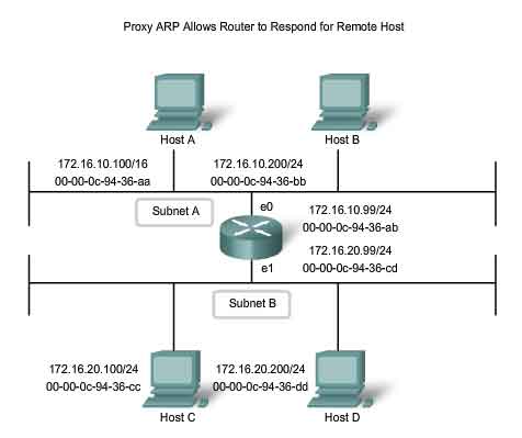
Proxy ARP
There are circumstances under which a host might send an ARP request seeking to map an IPv4 address outside of the range of the local network. In these cases, the device sends ARP requests for IPv4 addresses not on the local network instead of requesting the MAC address associated with the IPv4 address of the gateway. To provide a MAC address for these hosts, a router interface may use a proxy ARP to respond on behalf of these remote hosts. This means that the ARP cache of the requesting device will contain the MAC address of the gateway mapped to any IP addresses not on the local network. Using proxy ARP, a router interface acts as if it is the host with the IPv4 address requested by the ARP request. By "faking" its identity, the router accepts responsibility for routing packets to the "real" destination. One such use of this process is when an older implementation of IPv4 cannot determine whether the destination host is on the same logical network as the source. In these implementations, ARP always sends ARP requests for the destination IPv4 address. If proxy ARP is disabled on the router interface, these hosts cannot communicate out of the local network. Another case where a proxy ARP is used is when a host believes that it is directly connected to the same logical network as the destination host. This generally occurs when a host is configured with an improper mask. As shown in the figure, Host A has been improperly configured with a /16 subnet mask. This host believes that it is directly connected to all of the 172.16.0.0 /16 network instead of to the 172.16.10.0 /24 subnet. When attempts are made to communicate with any IPv4 host in the range of 172.16.0.1 to 172.16.255.254, Host A will send an ARP request for that IPv4 address. The router can use a proxy ARP to respond to requests for the IPv4 address of Host C (172.16.20.100) and Host D (172.16.20.200). Host A will subsequently have entries for these addresses mapped to the MAC address of the e0 interface of the router (00-00-0c-94-36-ab). Yet another use for a proxy ARP is when a host is not configured with a default gateway. Proxy ARP can help devices on a network reach remote subnets without the need to configure routing or a default gateway. By default, Cisco routers have proxy ARP enabled on LAN interfaces.
http://www.cisco.com/warp/public/105/5.html
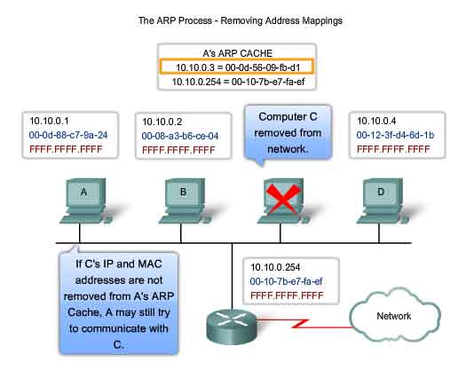
The ARP Process - Removing Address Mappings
For each device, an ARP cache timer removes ARP entries that have not been used for a specified period of time. The times differ depending on the device and its operating system. For example, some Windows operating systems store ARP cache entries for 2 minutes. If the entry is used again during that time, the ARP timer for that entry is extended to 10 minutes. Commands may also be used to manually remove all or some of the entries in the ARP table. After an entry has been removed, the process for sending an ARP request and receiving an ARP reply must occur again to enter the map in the ARP table. In the lab for this section, you will use the arp command to view and to clear the contents of a computer's ARP cache. Note that this command, despite its name, does not invoke the execution of the Address Resolution Protocol in any way. It is merely used to display, add, or remove the entries of the ARP table. ARP service is integrated within the IPv4 protocol and implemented by the device. Its operation is transparent to both upper layer applications and users.
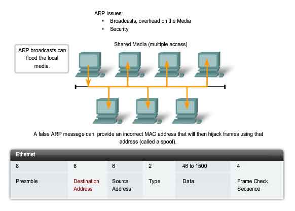
ARP Broadcasts - Issues
Overhead on the Media
As a broadcast frame, an ARP request is received and processed by every device on the local network. On a typical business network, these broadcasts would probably have minimal impact on network performance. However, if a large number of devices were to be powered up and all start accessing network services at the same time, there could be some reduction in performance for a short period of time. For example, if all students in a lab logged into classroom computers and attempted to access the Internet at the same time, there could be delays. However, after the devices send out the initial ARP broadcasts and have learned the necessary MAC addresses, any impact on the network will be minimized.
Security
In some cases, the use of ARP can lead to a potential security risk. ARP spoofing, or ARP poisoning, is a technique used by an attacker to inject the wrong MAC address association into a network by issuing fake ARP requests. An attacker forges the MAC address of a device and then frames can be sent to the wrong destination. Manually configuring static ARP associations is one way to prevent ARP spoofing. Authorized MAC addresses can be configured on some network devices to restrict network access to only those devices listed.