OSI Transport Layer
Roles of the Transport Layer
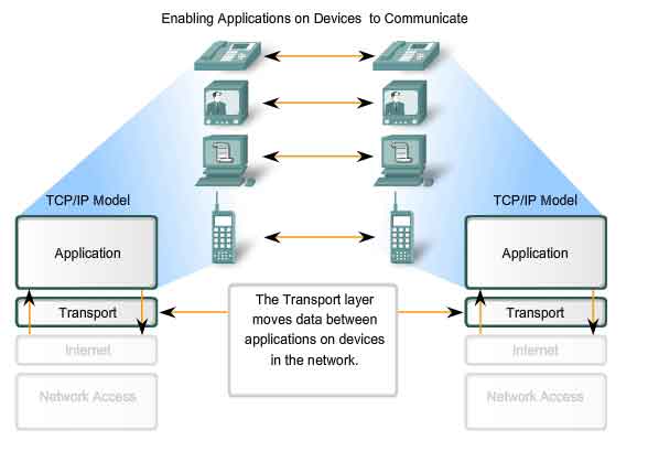
Purpose of the Transport Layer
The Transport layer provides for the segmentation of data and the control necessary to reassemble these pieces into the various communication streams. Its primary responsibilities to accomplish this are:
-
Tracking the individual communication between applications on the source and destination hosts
- Segmenting data and managing each piece
- Reassembling the segments into streams of application data
- Identifying the different applications
Tracking Individual Conversations
Any host may have multiple applications that are communicating across the network. Each of these applications will be communicating with one or more applications on remote hosts. It is the responsibility of the Transport layer to maintain the multiple communication streams between these applications.
Segmenting Data
As each application creates a stream data to be sent to a remote application, this data must be prepared to be sent across the media in manageable pieces. The Transport layer protocols describe services that segment this data from the Application layer. This includes the encapsulation required on each piece of data. Each piece of application data requires headers to be added at the Transport layer to indicate to which communication it is associated.
Reassembling Segments
At the receiving host, each piece of data may be directed to the appropriate application. Additionally, these individual pieces of data must also be reconstructed into a complete data stream that is useful to the Application layer. The protocols at the Transport layer describe the how the Transport layer header information is used to reassemble the data pieces into streams to be passed to the Application layer.
Identifying the Applications
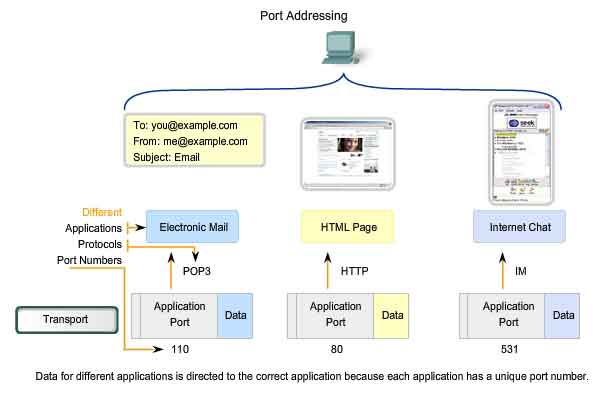
In order to pass data streams to the proper applications, the Transport layer must identify the target application. To accomplish this, the Transport layer assigns an application an identifier. The TCP/IP protocols call this identifier a port number. Each software process that needs to access the network is assigned a port number unique in that host. This port number is used in the transport layer header to indicate to which application that piece of data is associated. The Transport layer is the link between the Application layer and the lower layer that are responsible for network transmission. This layer accepts data from different conversations and passes it down to the lower layers as manageable pieces that can be eventually multiplexed over the media. Applications do not need to know the operational details of the network in use. The applications generate data that is sent from one application to another, without regard to the destination host type, the type of media over which the data must travel, the path taken by the data, the congestion on a link, or the size of the network. Additionally, the lower layers are not aware that there are multiple applications sending data on the network. Their responsibility is to deliver data to the appropriate device. The Transport layer then sorts these pieces before delivering them to the appropriate application.
Data Requirements Vary
Because different applications have different requirements, there are multiple Transport layer protocols. For some applications, segments must arrive in a very specific sequence in order to be processed successfully. In some cases, all of the data must be received for any of it to be of use. In other cases, an application can tolerate some loss of data during transmission over the network. In today's converged networks, applications with very different transport needs may be communicating on the same network. The different Transport layer protocols have different rules allowing devices to handle these diverse data requirements. Some protocols provide just the basic functions for efficiently delivering the data pieces between the appropriate applications. These types of protocols are useful for applications whose data is sensitive to delays. Other Transport layer protocols describe processes that provide additional features, such as ensuring reliable delivery between the applications. While these additional functions provide more robust communication at the Transport layer between applications, they have additional overhead and make larger demands on the network.
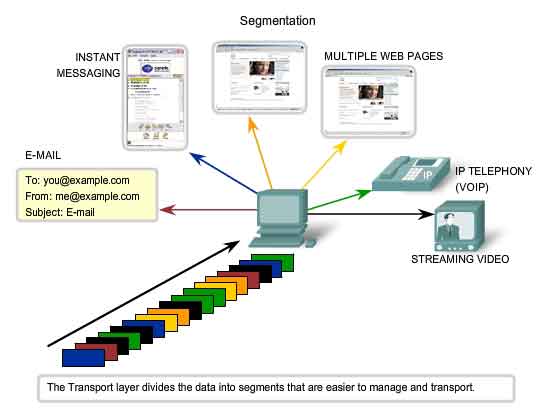
Separating Multiple Communications
Consider a computer connected to a network that is simultaneously receiving and sending e-mail and instant messages, viewing websites, and conducting a VoIP phone call. Each of these applications is sending and receiving data over the network at the same time. However, data from the phone call is not directed to the web browser, and text from an instant message does not appear in an e-mail. Further, users require that an e-mail or web page be completely received and presented for the information to be considered useful. Slight delays are considered acceptable to ensure that the complete information is received and presented. In contrast, occasionally missing small parts of a telephone conversation might be considered acceptable. One can either infer the missing audio from the context of the conversation or ask the other person to repeat what they said. This is considered preferable to the delays that would result from asking the network to manage and resend missing segments. In this example, the user - not the network - manages the resending or replacement of missing information.
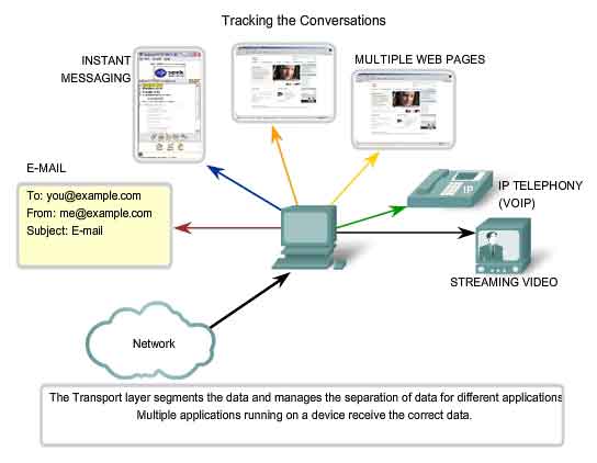
As explained in a previous chapter, sending some types of data - a video for example - across a network as one complete communication stream could prevent other communications from occurring at the same time. It also makes error recovery and retransmission of damaged data difficult. Dividing data into small parts, and sending these parts from the source to the destination, enables many different communications to be interleaved (multiplexed) on the same network. Segmentation of the data, in accordance with Transport layer protocols, provides the means to both send and receive data when running multiple applications concurrently on a computer. Without segmentation, only one application, the streaming video for example, would be able to receive data. You could not receive e-mails, chat on instant messenger, or view web pages while also viewing the video. At the Transport layer, each particular set of pieces flowing between a source application and a destination application is known as a conversation. To identify each segment of data, the Transport layer adds to the piece a header containing binary data. This header contains fields of bits. It is the values in these fields that enable different Transport layer protocols to perform different functions.
Controlling the Conversations
The primary functions specified by all Transport layer protocols include:
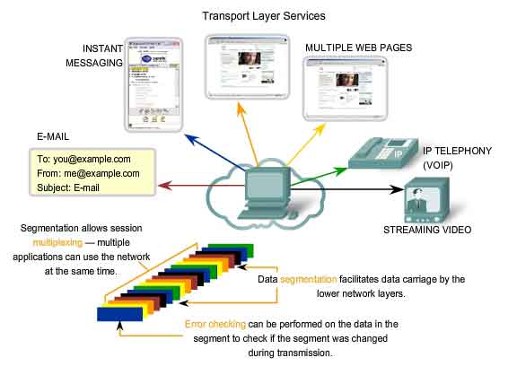
Segmentation and Reassembly - Most networks have a limitation on the amount of data that can be included in a single PDU. The Transport layer divides application data into blocks of data that are an appropriate size. At the destination, the Transport layer reassembles the data before sending it to the destination application or service.
Conversation Multiplexing - There may be many applications or services running on each host in the network. Each of these applications or services is assigned an address known as a port so that the Transport layer can determine with which application or service the data is identified. In addition to using the information contained in the headers, for the basic functions of data segmentation and reassembly, some protocols at the Transport layer provide:
-
Connection-oriented conversations
- Reliable delivery
- Ordered data reconstruction
- Flow control
Establishing a Session
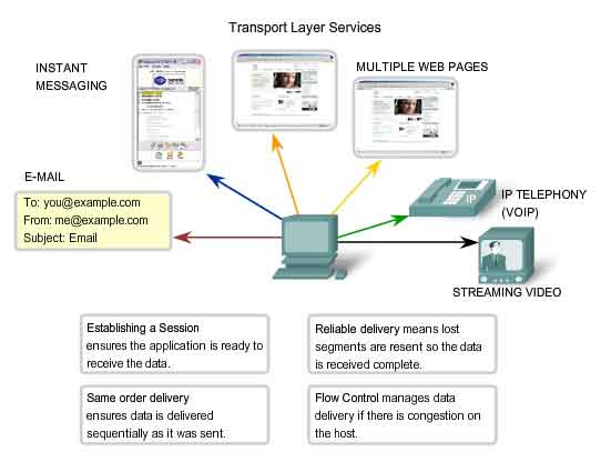
The Transport layer can provide this connection orientation by creating a sessions between the applications. These connections prepare the applications to communicate with each other before any data is transmitted. Within these sessions, the data for a communication between the two applications can be closely managed.
Reliable Delivery
For many reasons, it is possible for a piece of data to become corrupted, or lost completely, as it is transmitted over the network. The Transport layer can ensure that all pieces reach their destination by having the source device to retransmit any data that is lost.
Same Order Delivery
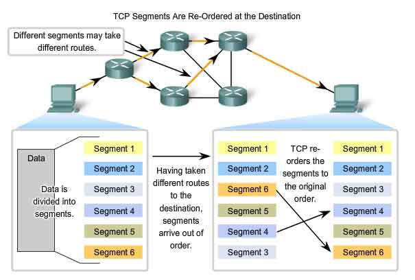
Because networks may provide multiple routes that can have different transmission times, data can arrive in the wrong order. By numbering and sequencing the segments, the Transport layer can ensure that these segments are reassembled into the proper order.
Flow Control
Network hosts have limited resources, such as memory or bandwidth. When Transport layer is aware that these resources are overtaxed, some protocols can request that the sending application reduce the rate of data flow. This is done at the Transport layer by regulating the amount of data the source transmits as a group. Flow control can prevent the loss of segments on the network and avoid the need for retransmission.
Supporting Reliable Communication
Recall that the primary function of the Transport layer is to manage the application data for the conversations between hosts. However, different applications have different requirements for their data, and therefore different Transport protocols have been developed to meet these requirements. A Transport layer protocol can implement a method to ensure reliable delivery of the data. In networking terms, reliability means ensuring that each piece of data that the source sends arrives at the destination. At the Transport layer the three basic operations of reliability are:
-
tracking transmitted data
- acknowledging received data
- retransmitting any unacknowledged data
This requires the processes of Transport layer of the source to keep track of all the data pieces of each conversation and the retransmit any of data that did were not acknowledged by the destination. The Transport layer of the receiving host must also track the data as it is received and acknowledge the receipt of the data. These reliability processes place additional overhead on the network resources due to the acknowledgement, tracking, and retransmission. To support these reliability operations, more control data is exchanged between the sending and receiving hosts. This control information is contained in the Layer 4 header. This creates a trade-off between the value of reliability and the burden it places on the network. Application developers must choose which transport protocol type is appropriate based on the requirements of their applications. At the Transport layer, there are protocols that specify methods for either reliable, guaranteed delivery or best-effort delivery. In the context of networking, best-effort delivery is referred to as unreliable, because there is no acknowledgement that the data is received at the destination.
Determining the Need for Reliability
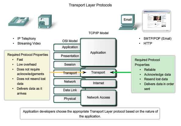
Applications, such as databases, web pages, and e-mail, require that all of the sent data arrive at the destination in its original condition, in order for the data to be useful. Any missing data could cause a corrupt communication that is either incomplete or unreadable. Therefore, these applications are designed to use a Transport layer protocol that implements reliability. The additional network overhead is considered to be required for these applications. Other applications are more tolerant of the loss of small amounts of data. For example, if one or two segments of a video stream fail to arrive, it would only create a momentary disruption in the stream. This may appear as distortion in the image but may not even be noticeable to the user. Imposing overhead to ensure reliability for this application could reduce the usefulness of the application. The image in a streaming video would be greatly degraded if the destination device had to account for lost data and delay the stream while waiting for its arrival. It is better to render the best image possible at the time with the segments that arrive and forego reliability. If reliability is required for some reason, these applications can provide error checking and retransmission requests.
TCP and UDP
The two most common Transport layer protocols of TCP/IP protocol suite are Transmission Control Protocol (TCP) and User Datagram Protocol (UDP). Both protocols manage the communication of multiple applications. The differences between the two are the specific functions that each protocol implements.
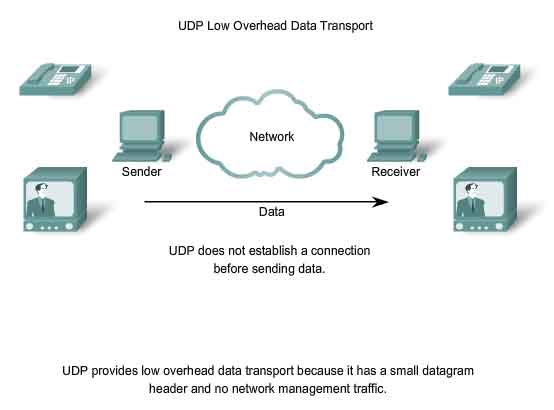
User Datagram Protocol (UDP)
UDP is a simple, connectionless protocol, described in RFC 768. It has the advantage of providing for low overhead data delivery. The pieces of communication in UDP are called datagrams. These datagrams are sent as "best effort" by this Transport layer protocol.
Applications that use UDP include: Domain Name System (DNS), Video Streaming, Voice over IP (VoIP)
Transmission Control Protocol (TCP)
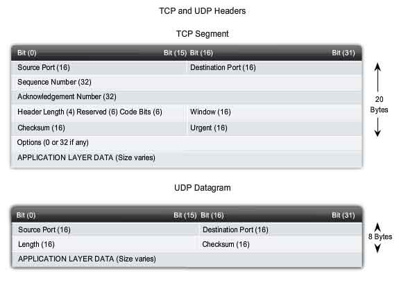
TCP is a connection-oriented protocol, described in RFC 793. TCP incurs additional overhead to gain functions. Additional functions specified by TCP are the same order delivery, reliable delivery, and flow control. Each TCP segment has 20 bytes of overhead in the header encapsulating the Application layer data, whereas each UDP segment only has 8 bytes of overhead. See the figure for a comparison.
Applications that use TCP are: Web Browsers, E-mail, File Transfers
Port Addressing
Identifying the Conversations
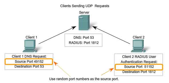
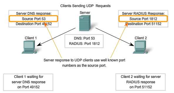
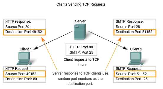
Consider the earlier example of a computer simultaneously receiving and sending e-mail, instant messages, web pages, and a VoIP phone call. The TCP and UDP based services keep track of the various applications that are communicating. To differentiate the segments and datagrams for each application, both TCP and UDP have header fields that can uniquely identify these applications. These unique identifiers are the port numbers. In the header of each segment or datagram, there is a source and destination port. The source port number is the number for this communication associated with the originating application on the local host. The destination port number is the number for this communication associated with the destination application on the remote host. Port numbers are assigned in various ways, depending on whether the message is a request or a response. While server processes have static port numbers assigned to them, clients dynamically choose a port number for each conversation. When a client application sends a request to a server application, the destination port contained in the header is the port number that is assigned to the service daemon running on the remote host. The client software must know what port number is associated with the server process on the remote host. This destination port number is configured, either by default or manually. For example, when a web browser application makes a request to a web server, the browser uses TCP and port number 80 unless otherwise specified. This is because TCP port 80 is the default port assigned to web-serving applications. Many common applications have default port assignments. The source port in a segment or datagram header of a client request is randomly generated. As long as it does not conflict with other ports in use on the system, the client can choose any port number. This port number acts like a return address for the requesting application. The Transport layer keeps track of this port and the application that initiated the request so that when a response is returned, it can be forwarded to the correct application. The requesting application port number is used as the destination port number in the response coming back from the server. The combination of the Transport layer port number and the Network layer IP address assigned to the host uniquely identifies a particular process running on a specific host device. This combination is called a socket. Occasionally, you may find the terms port number and socket used interchangeably. In the context of this course, the term socket refers only to the unique combination of IP address and port number. A socket pair, consisting of the source and destination IP addresses and port numbers, is also unique and identifies the conversation between the two hosts. For example, an HTTP web page request being sent to a web server (port 80) running on a host with a Layer 3 IPv4 address of 192.168.1.20 would be destined to socket 192.168.1.20:80. If the web browser requesting the web page is running on host 192.168.100.48 and the Dynamic port number assigned to the web browser is 49152, the socket for the web page would be 192.168.100.48:49152.
The Internet Assigned Numbers Authority (IANA) assigns port numbers. IANA is a standards body that is responsible for assigning various addressing standards.
There are different types of port numbers:
Well Known Ports (Numbers 0 to 1023) - These numbers are reserved for services and applications. They are commonly used for applications such as HTTP (web server) POP3/SMTP (e-mail server) and Telnet. By defining these well-known ports for server applications, client applications can be programmed to request a connection to that specific port and its associated service.
Registered Ports (Numbers 1024 to 49151) - These port numbers are assigned to user processes or applications. These processes are primarily individual applications that a user has chosen to install rather than common applications that would receive a Well Known Port. When not used for a server resource, these ports may also be used dynamically selected by a client as its source port.
Dynamic or Private Ports (Numbers 49152 to 65535) - Also known as Ephemeral Ports, these are usually assigned dynamically to client applications when initiating a connection. It is not very common for a client to connect to a service using a Dynamic or Private Port (although some peer-to-peer file sharing programs do).
Using both TCP and UDP
Some applications may use both TCP and UDP. For example, the low overhead of UDP enables DNS to serve many client requests very quickly. Sometimes, however, sending the requested information may require the reliability of TCP. In this case, the well known port number of 53 is used by both protocols with this service.
Links
A current list of port numbers can be found athttp://www.iana.org/assignments/port-numbers.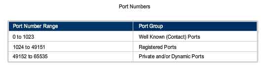
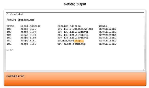
Sometimes it is necessary to know which active TCP connections are open and running on a networked host. Netstat is an important network utility that can be used to verify those connections. Netstat lists the protocol in use, the local address and port number, the foreign address and port number, and the state of the connection. Unexplained TCP connections can pose a major security threat. This is because they can indicate that something or someone is connected to the local host. Additionally, unnecessary TCP connections can consume valuable system resources thus slowing down the host's performance. Netstat should be used to examine the open connections on a host when performance appears to be compromised. Many useful options are available for the netstat command.
Segmentation and Reassembly - Divide and Conquer
A previous chapter explained how PDUs are built by passing data from an application down through the various protocols to create a PDU that is then transmitted on the medium. At the destination host, this process is reversed until the data can be passed up to the application. Some applications transmit large amounts of data - in some cases, many gigabytes. It would be impractical to send all of this data in one large piece. No other network traffic could be transmitted while this data was being sent. A large piece of data could take minutes or even hours to send. In addition, if there were any error, the entire data file would have to be lost or resent. Network devices would not have memory buffers large enough to store this much data while it is transmitted or received. The limit varies depending on the networking technology and specific physical medium being in use.
Dividing application data into pieces both ensures that data is transmitted within the limits of the media and that data from different applications can be multiplexed on to the media.
TCP and UDP Handle Segmentation Differently.
In TCP, each segment header contains a sequence number. This sequence number allows the Transport layer functions on the destination host to reassemble segments in the order in which they were transmitted. This ensures that the destination application has the data in the exact form the sender intended. Although services using UDP also track the conversations between applications, they are not concerned with the order in which the information was transmitted, or in maintaining a connection. There is no sequence number in the UDP header. UDP is a simpler design and generates less overhead than TCP, resulting in a faster transfer of data. Information may arrive in a different order than it was transmitted because different packets may take different paths through the network. An application that uses UDP must tolerate the fact that data may not arrive in the order in which it was sent.

The TCP Protocol - Communicating with Reliability
TCP - Making Conversations Reliable
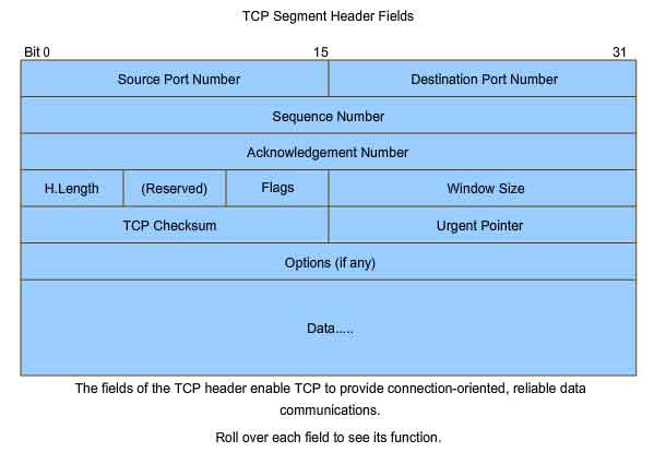
The key distinction between TCP and UDP is reliability. The reliability of TCP communication is performed using connection-oriented sessions. Before a host using TCP sends data to another host, the Transport layer initiates a process to create a connection with the destination. This connection enables the tracking of a session, or communication stream between the hosts. This process ensures that each host is aware of and prepared for the communication. A complete TCP conversation requires the establishment of a session between the hosts in both directions. After a session has been established, the destination sends acknowledgements to the source for the segments that it receives. These acknowledgements form the basis of reliability within the TCP session. As the source receives an acknowledgement, it knows that the data has been successfully delivered and can quit tracking that data. If the source does not receive an acknowledgement within a predetermined amount of time, it retransmits that data to the destination. Part of the additional overhead of using TCP is the network traffic generated by acknowledgements and retransmissions. The establishment of the sessions creates overhead in the form of additional segments being exchanged. There is also additional overhead on the individual hosts created by the necessity to keep track of which segments are awaiting acknowledgement and by the retransmission process. This reliability is achieved by having fields in the TCP segment, each with a specific function, as shown in the figure. These fields will be discussed later in this section.
TCP Server Processes
As discussed in the previous chapter, application processes run on servers. These processes wait until a client initiates communication with a request for information or other services. Each application process running on the server is configured to use a port number, either by default or manually by a system administrator. An individual server cannot have two services assigned to the same port number within the same Transport layer services. A host running a web server application and a file transfer application cannot have both configured to use the same port (for example, TCP port 8080). When an active server application is assigned to a specific port, that port is considered to be "open" on the server. This means that the Transport layer accepts and processes segments addressed to that port. Any incoming client request addressed to the correct socket is accepted and the data is passed to the server application. There can be many simultaneous ports open on a server, one for each active server application. It is common for a server to provide more than one service, such as a web server and an FTP server, at the same time. One way to improve security on a server is to restrict server access to only those ports associated with the services and applications that should be accessible to authorized requestors. The figure shows the typical allocation of source and destination ports in TCP client/server operations.
TCP Connection Establishment and Termination
When two hosts communicate using TCP, a connection is established before data can be exchanged. After the communication is completed, the sessions are closed and the connection is terminated. The connection and session mechanisms enable TCP's reliability function.
The host tracks each data segment within a session and exchanges information about what data is received by each host using the information in the TCP header. Each connection represents two one-way communication streams, or sessions. To establish the connection, the hosts perform a three-way handshake. Control bits in the TCP header indicate the progress and status of the connection. The three-way handshake:
-
Establishes that the destination device is present on the network
- Verifies that the destination device has an active service and is accepting requests on the destination port number that the initiating client intends to use for the session
- Informs the destination device that the source client intends to establish a communication session on that port number
In TCP connections, the host serving as a client initiates the session to the server. The three steps in TCP connection establishment are:
1. The initiating client sends a segment containing an initial sequence value, which serves as a request to the server to begin a communications session.
2. The server responds with a segment containing an acknowledgement value equal to the received sequence value plus 1, plus its own synchronizing sequence value. The value is one greater than the sequence number because the ACK is always the next expected Byte or Octet. This acknowledgement value enables the client to tie the response back to the original segment that it sent to the server.
3. Initiating client responds with an acknowledgement value equal to the sequence value it received plus one. This completes the process of establishing the connection.
To understand the three-way handshake process, it is important to look at the various values that the two hosts exchange. Within the TCP segment header, there are six 1-bit fields that contain control information used to manage the TCP processes. Those fields are:
URG - Urgent pointer field significant
ACK - Acknowledgement field significant
PSH - Push function
RST - Reset the connection
SYN - Synchronize sequence numbers
FIN - No more data from sender
These fields are referred to as flags, because the value of one of these fields is only 1 bit and, therefore, has only two values: 1 or 0. When a bit value is set to 1, it indicates what control information is contained in the segment.
Using a four-step process, flags are exchanged to terminate a TCP connection.
TCP Three-Way Handshake
Using the Wireshark outputs, you can examine the operation of the TCP 3-way handshake:
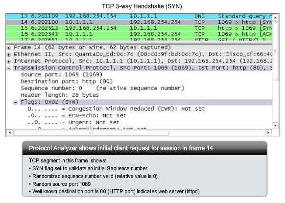
Step 1
A TCP client begins the three-way handshake by sending a segment with the SYN (Synchronize Sequence Number) control flag set, indicating an initial value in the sequence number field in the header. This initial value for the sequence number, known as the Initial Sequence Number (ISN), is randomly chosen and is used to begin tracking the flow of data from the client to the server for this session. The ISN in the header of each segment is increased by one for each byte of data sent from the client to the server as the data conversation continues. As shown in the figure, output from a protocol analyzer shows the SYN control flag and the relative sequence number. The SYN control flag is set and the relative sequence number is at 0. Although the protocol analyzer in the graphic indicates the relative values for the sequence and acknowledgement numbers, the true values are 32 bit binary numbers. We can determine the actual numbers sent in the segment headers by examining the Packet Bytes pane. Here you can see the four bytes represented in hexadecimal.
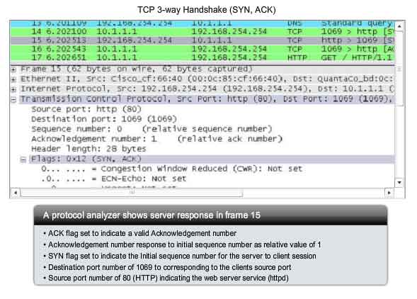
Step 2
The TCP server needs to acknowledge the receipt of the SYN segment from the client to establish the session from the client to the server. To do so, the server sends a segment back to the client with the ACK flag set indicating that the Acknowledgment number is significant. With this flag set in the segment, the client recognizes this as an acknowledgement that the server received the SYN from the TCP client. The value of the acknowledgment number field is equal to the client initial sequence number plus 1. This establishes a session from the client to the server. The ACK flag will remain set for the balance of the session. Recall that the conversation between the client and the server is actually two one-way sessions: one from the client to the server, and the other from the server to the client. In this second step of the three-way handshake, the server must initiate the response from the server to the client. To start this session, the server uses the SYN flag in the same way that the client did. It sets the SYN control flag in the header to establish a session from the server to the client. The SYN flag indicates that the initial value of the sequence number field is in the header. This value will be used to track the flow of data in this session from the server back to the client. As shown in the figure, the protocol analyzer output shows that the ACK and SYN control flags are set and the relative sequence and acknowledgement numbers are shown.
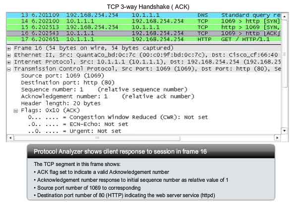
Step 3
Finally, the TCP client responds with a segment containing an ACK that is the response to the TCP SYN sent by the server. There is no user data in this segment. The value in the acknowledgment number field contains one more than the initial sequence number received from the server. Once both sessions are established between client and server, all additional segments exchanged in this communication will have the ACK flag set. As shown in the figure, the protocol analyzer output shows the ACK control flag set and the relative sequence and acknowledgement numbers are shown.
Security can be added to the data network by:
-
Denying the establishment of TCP sessions
- Only allowing sessions to be established for specific services
- Only allowing traffic as a part of already established sessions
This security can be implemented for all TCP sessions or only for selected sessions.
TCP Session Termination
To close a connection, the FIN (Finish) control flag in the segment header must be set. To end each one-way TCP session, a two-way handshake is used, consisting of a FIN segment and an ACK segment. Therefore, to terminate a single conversation supported by TCP, four exchanges are needed to end both sessions. Note: In this explanation, the terms client and server are used in this description as a reference for simplicity, but the termination process can be initiated by any two hosts that complete the session:
1. When the client has no more data to send in the stream, it sends a segment with the FIN flag set.
2. The server sends an ACK to acknowledge the receipt of the FIN to terminate the session from client to server.
3. The server sends a FIN to the client, to terminate the server to client session.
4. The client responds with an ACK to acknowledge the FIN from the server.
When the client end of the session has no more data to transfer, it sets the FIN flag in the header of a segment. Next, the server end of the connection will send a normal segment containing data with the ACK flag set using the acknowledgment number, confirming that all the bytes of data have been received. When all segments have been acknowledged, the session is closed. The session in the other direction is closed using the same process. The receiver indicates that there is no more data to send by setting the FIN flag in the header of a segment sent to the source. A return acknowledgement confirms that all bytes of data have been received and that session is, in turn, closed. As shown in the figure, the FIN and ACK control flags are set in the segment header, thereby closing a HTTP session.
It is also possible to terminate the connection by a three-way handshake. When the client has no more data to send, it sends a FIN to the server. If the server also has no more data to send, it can reply with both the FIN and ACK flags set, combining two steps into one. The client replies with an ACK.
Managing TCP Sessions
TCP Segment Reassembly
Resequencing Segments to Order Transmitted
When services send data using TCP, segments may arrive at their destination out of order. For the original message to be understood by the recipient, the data in these segments is reassembled into the original order. Sequence numbers are assigned in the header of each packet to achieve this goal. During session setup, an initial sequence number (ISN) is set. This initial sequence number represents the starting value for the bytes for this session that will be transmitted to the receiving application. As data is transmitted during the session, the sequence number is incremented by the number of bytes that have been transmitted. This tracking of data byte enables each segment to be uniquely identified and acknowledged. Missing segments can be identified. Segment sequence numbers enable reliability by indicating how to reassemble and reorder received segments, as shown in the figure. The receiving TCP process places the data from a segment into a receiving buffer. Segments are placed in the proper sequence number order and passed to the Application layer when reassembled. Any segments that arrive with noncontiguous sequence numbers are held for later processing. Then, when the segments with the missing bytes arrive, these segments are processed.
TCP Acknowledgement with Windowing
Confirming Receipt of Segments
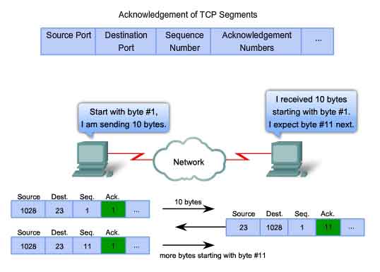
One of TCP's functions is making sure that each segment reaches its destination. The TCP services on the destination host acknowledge the data that it has received to the source application. The segment header sequence number and acknowledgement number are used together to confirm receipt of the bytes of data contained in the segments. The sequence number is the relative number of bytes that have been transmitted in this session plus 1 (which is the number of the first data byte in the current segment). TCP uses the acknowledgement number in segments sent back to the source to indicate the next byte in this session that the receiver expects to receive. This is called expectational acknowledgement. The source is informed that the destination has received all bytes in this data stream up to, but not including, the byte indicated by the acknowledgement number. The sending host is expected to send a segment that uses a sequence number that is equal to the acknowledgement number. Remember, each connection is actually two one-way sessions. Sequence numbers and acknowledgement numbers are being exchanged in both directions. In the example in the figure, the host on the left is sending data to the host on the right. It sends a segment containing 10 bytes of data for this session and a sequence number equal to 1 in the header. The receiving host on the right receives the segment at Layer 4 and determines that the sequence number is 1 and that it has 10 bytes of data. The host then sends a segment back to the host on the left to acknowledge the receipt of this data. In this segment, the host sets the acknowledgement number to 11 to indicate that the next byte of data it expects to receive in this session is byte number 11. When the sending host on the left receives this acknowledgement, it can now send the next segment containing data for this session starting with byte number 11. Looking at this example, if the sending host had to wait for acknowledgement of the receipt of each 10 bytes, the network would have a lot of overhead. To reduce the overhead of these acknowledgements, multiple segments of data can be sent before and acknowledged with a single TCP message in the opposite direction. This acknowledgement contains an acknowledgement number based on the total number of bytes received in the session. For example, starting with a sequence number of 2000, if 10 segments of 1000 bytes each were received, an acknowledgement number of 12001 would be returned to the source. The amount of data that a source can transmit before an acknowledgement must be received is called the window size. Window Size is a field in the TCP header that enables the management of lost data and flow control.
TCP Retransmission
Handling Segment Loss
No matter how well designed a network is, data loss will occasionally occur. Therefore, TCP provides methods of managing these segment losses. Among these is a mechanism to retransmit segments with unacknowledged data. A destination host service using TCP usually only acknowledges data for contiguous sequence bytes. If one or more segments are missing, only the data in the segments that complete the stream are acknowledged. For example, if segments with sequence numbers 1500 to 3000 and 3400 to 3500 were received, the acknowledgement number would be 3001. This is because there are segments with the sequence numbers 3001 to 3399 that have not been received. When TCP at the source host has not received an acknowledgement after a predetermined amount of time, it will go back to the last acknowledgement number that it received and retransmit data from that point forward. The retransmission process is not specified by the RFC, but is left up to the particular implementation of TCP. For a typical TCP implementation, a host may transmit a segment, put a copy of the segment in a retransmission queue, and start a timer. When the data acknowledgment is received, the segment is deleted from the queue. If the acknowledgment is not received before the timer expires, the segment is retransmitted. The animation demonstrates the retransmission of lost segments. Hosts today may also employ an optional feature called Selective Acknowledgements. If both hosts support Selective Acknowledgements, it is possible for the destination to acknowledge bytes in discontinuous segments and the host would only need to retransmit the missing data.
TCP Congestion Control - Minimizing Segment Loss
Flow Control
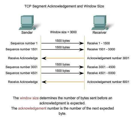
TCP also provides mechanisms for flow control. Flow control assists the reliability of TCP transmission by adjusting the effective rate of data flow between the two services in the session. When the source is informed that the specified amount of data in the segments is received, it can continue sending more data for this session. This Window Size field in the TCP header specifies the amount of data that can be transmitted before an acknowledgement must be received. The initial window size is determined during the session startup via the three-way handshake. TCP feedback mechanism adjusts the effective rate of data transmission to the maximum flow that the network and destination device can support without loss. TCP attempts to manage the rate of transmission so that all data will be received and retransmissions will be minimized. See the figure for a simplified representation of window size and acknowledgements. In this example, the initial window size for a TCP session represented is set to 3000 bytes. When the sender has transmitted 3000 bytes, it waits for an acknowledgement of these bytes before transmitting more segments in this session. Once the sender has received this acknowledgement from the receiver, the sender can transmit an additional 3000 bytes. During the delay in receiving the acknowledgement, the sender will not be sending any additional segments for this session. In periods when the network is congested or the resources of the receiving host are strained, the delay may increase. As this delay grows longer, the effective transmission rate of the data for this session decreases. The slowdown in data rate helps reduce the resource contention.
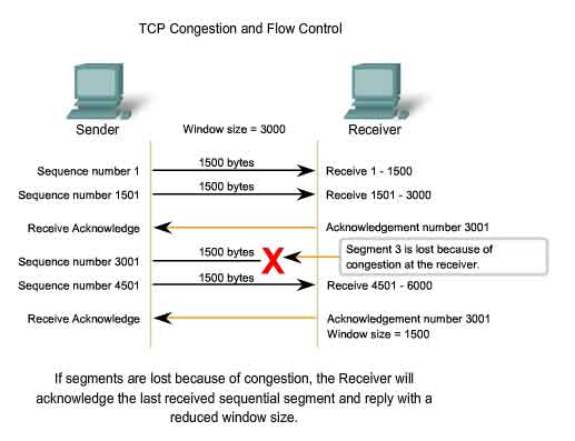
Reducing Window Size
Another way to control the data flow is to use dynamic window sizes. When network resources are constrained, TCP can reduce the window size to require that received segments be acknowledged more frequently. This effectively slows down the rate of transmission because the source waits for data to be acknowledged more frequently. The TCP receiving host sends the window size value to the sending TCP to indicate the number of bytes that it is prepared to receive as a part of this session. If the destination needs to slow down the rate of communication because of limited buffer memory, it can send a smaller window size value to the source as part of an acknowledgement. As shown in the figure, if a receiving host has congestion, it may respond to the sending host with a segment with a reduced window size. In this graphic, there was a loss of one of the segments. The receiver changed the window field in the TCP header of the returning segments in this conversation from 3000 down to 1500. This caused the sender to reduce the window size to 1500. After periods of transmission with no data losses or constrained resources, the receiver will begin to increase the window field. This reduces the overhead on the network because fewer acknowledgments need to be sent. Window size will continue to increase until there is data loss, which will cause the window size to be decreased. This dynamic increasing and decreasing of window size is a continuous process in TCP, which determines the optimum window size for each TCP session. In highly efficient networks, window sizes may become very large because data is not being lost. In networks where the underlying infrastructure is being stressed, the window size will likely remain small.
Details of TCP's various congestion management features can be found in RFC 2581.
The UDP Protocol - Communicating with Low Overhead
UDP - Low Overhead vs. Reliability
UDP is a simple protocol that provides the basic Transport layer functions. It much lower overhead than TCP, since it is not connection-oriented and does not provide the sophisticated retransmission, sequencing, and flow control mechanisms. This does not mean that applications that use UDP are always unreliable. It simply means that these functions are not provided by the Transport layer protocol and must be implemented elsewhere if required. Although the total amount of UDP traffic found on a typical network is often relatively low, key Application layer protocols that use UDP include:
-
Domain Name System (DNS)
- Simple Network Management Protocol (SNMP)
- Dynamic Host Configuration Protocol (DHCP)
- Routing Information Protocol (RIP)
- Trivial File Transfer Protocol (TFTP)
- Online games
Some applications, such as online games or VoIP, can tolerate some loss of some data. If these applications used TCP, they may experience large delays while TCP detects data loss and retransmits data. These delays would be more detrimental to the application than small data losses. Some applications, such as DNS, will simply retry the request if they do not receive a response, and therefore they do not need TCP to guarantee the message delivery. The low overhead of UDP makes it very desirable for such applications.
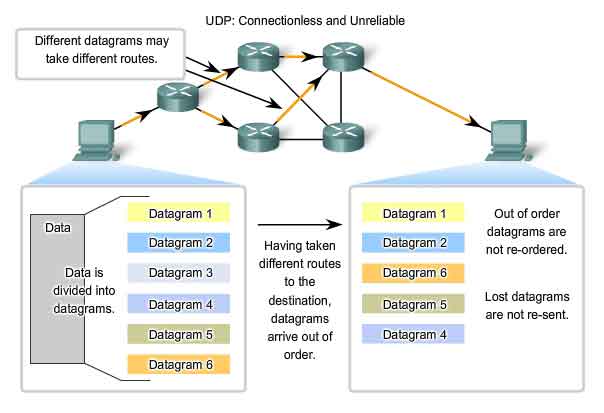
UDP Datagram Reassembly
Because UDP is connectionless, sessions are not established before communication takes place as they are with TCP. UDP is said to be transaction-based. In other words, when an application has data to send, it simply sends the data. Many applications that use UDP send small amounts of data that can fit in one segment. However, some applications will send larger amounts of data that must be split into multiple segments The UDP PDU is referred to as a datagram, although the terms segment and datagram are sometimes used interchangeably to describe a Transport layer PDU. When multiple datagrams are sent to a destination, they may take different paths and arrive in the wrong order. UDP does not keep track of sequence numbers the way TCP does. UDP has no way to reorder the datagrams into their transmission order. See the figure. Therefore, UDP simply reassembles the data in the order that it was received and forwards it to the application. If the sequence of the data is important to the application, the application will have to identify the proper sequence of the data and determine how the data should be processed.
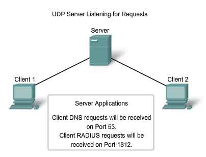
UDP Server Processes and Requests
Like TCP-based applications, UDP-based server applications are assigned Well Known or Registered port numbers. When these applications or processes are running, they will accept the data matched with the assigned port number. When UDP receives a datagram destined for one of these ports, it forwards the application data to the appropriate application based on its port number.
UDP Client Processes
As with TCP, client/server communication is initiated by a client application that is requesting data from a server process. The UDP client process randomly selects a port number from the dynamic range of port numbers and uses this as the source port for the conversation. The destination port will usually be the Well Known or Registered port number assigned to the server process. Randomized source port numbers also help with security. If there is a predictable pattern for destination port selection, an intruder can more easily simulate access to a client by attempting to connect to the port number most likely to be open. Because there is no session to be created with UDP, as soon as the data is ready to be sent and the ports identified, UDP can form the datagram and pass it to the Network layer to be addressed and sent on the network. Remember, once a client has chosen the source and destination ports, the same pair of ports is used in the header of all datagrams used in the transaction. For the data returning to the client from the server, the source and destination port numbers in the datagram header are reversed.