

Addressing the Network - IPv4
IPv4 Addresses
The Anatomy of an IPv4 Address
Each device on a network must be uniquely defined. At the Network layer, the packets of the communication need to be identified with the source and destination addresses of the two end systems. With IPv4, this means that each packet has a 32-bit source address and a 32-bit destination address in the Layer 3 header. These addresses are used in the data network as binary patterns. Inside the devices, digital logic is applied for their interpretation. For us in the human network, a string of 32 bits is difficult to interpret and even more difficult to remember. Therefore, we represent IPv4 addresses using dotted decimal format.
Dotted Decimal
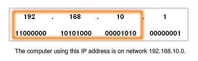
Binary patterns representing IPv4 addresses are expressed as dotted decimals by separating each byte of the binary pattern, called an octet, with a dot. It is called an octet because each decimal number represents one byte or 8 bits.
For example, the address:
10101100000100000000010000010100
is expressed in dotted decimal as:
172.16.4.20
Keep in mind that devices use binary logic. The dotted decimal format is used to make it easier for people to use and remember addresses.
Network and Host Portions
For each IPv4 address, some portion of the high-order bits represents the network address. At Layer 3, we define a network as a group of hosts that have identical bit patterns in the network address portion of their addresses. Although all 32 bits define the IPv4 host address, we have a variable number of bits that are called the host portion of the address. The number of bits used in this host portion determines the number of hosts that we can have within the network. For example, if we need to have at least 200 hosts in a particular network, we would need to use enough bits in the host portion to be able to represent at least 200 different bit patterns. To assign a unique address to 200 hosts, we would use the entire last octet. With 8 bits, a total of 256 different bit patterns can be achieved. This would mean that the bits for the upper three octets would represent the network portion.
Note: Calculating the number of hosts and determining which portion of the 32 bits refers to the network will be covered later in this chapter.
Knowing the Numbers - Binary to Decimal Conversion
To understand the operation of a device in a network, we need to look at addresses and other data the way the device does - in binary notation. This means that we need to have some skill in binary to decimal conversion. Data represented in binary may represent many different forms of data to the human network. In this discussion, we refer to binary as it relates to IPv4 addressing. This means that we look at each byte (octet) as a decimal number in the range of 0 to 255.
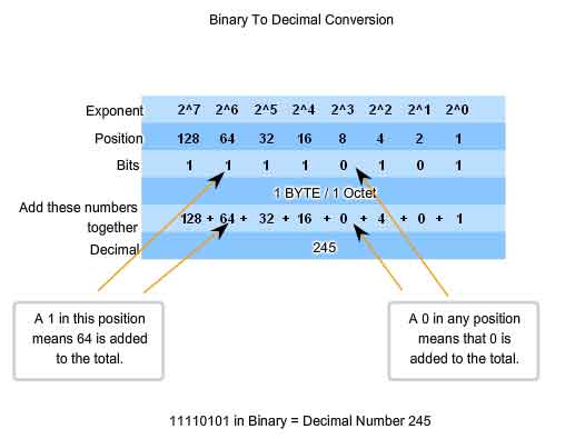
Positional Notation
Learning to convert binary to decimal requires an understanding of the mathematical basis of a numbering system called positional notation. Positional notation means that a digit represents different values depending on the position it occupies. More specifically, the value that a digit represents is that value multiplied by the power of the base, or radix, represented by the position the digit occupies. Some examples will help to clarify how this system works. For the decimal number 245, the value that the 2 represents is 2*10^2 (2 times 10 to the power of 2). The 2 is in what we commonly refer to as the "100s" position. Positional notation refers to this position as the base^2 position because the base, or radix, is 10 and the power is 2.
Using positional notation in the base 10 number system, 245 represents:
245 = (2 * 10^2) + (4 * 10^1) + (5 * 10^0)
or
245 = (2 * 100) + (4 * 10) + (5 * 1)
Binary Numbering System
In the binary numbering system, the radix is 2. Therefore, each position represents increasing powers of 2. In 8-bit binary numbers, the positions represent these quantities:
2^7 2^6 2^5 2^4 2^32^2 2^1 2^0
128 64 32 16 8 4 2 1
The base 2 numbering system only has two digits: 0 and 1.
When we interpret a byte as a decimal number, we have the quantity that position represents if the digit is a 1 and we do not have that quantity if the digit is a 0.
1 1 1 1 1 1 1 1
128 64 32 16 8 4 2 1
A 1 in each position means that we add the value for that position to the total. This is the addition when there is a 1 in each position of an octet. The total is 255.
128 + 64 + 32 + 16 + 8 + 4 + 2 + 1 = 255
A 0 in each position indicates that the value for that position is not added to the total. A 0 in every position yields a total of 0.
0 0 0 0 0 0 0 0
128 64 32 16 8 4 2 1
0 + 0 + 0 + 0 + 0 + 0 + 0 + 0 = 0
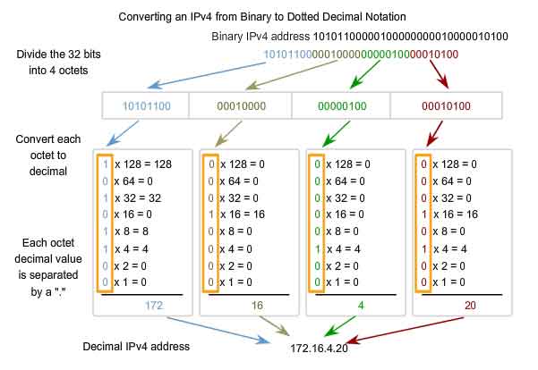
See the figure for the steps to convert a binary address to a decimal address.
In the example, the binary number:
10101100000100000000010000010100
Is converted to:
172.16.4.20
Keep these steps in mind:
Divide the 32 bits into 4 octets.
Convert each octet to decimal.
Add a "dot" between each decimal.
Knowing the Numbers - Decimal to Binary Conversions
Not only do we need to be able to convert binary to decimal, we also need to be able to convert decimal to binary. We often need to examine an individual octet of an address that is given in dotted decimal notation. Such is the case when the network bits and host bits divide an octet. As an example, if a host with the 172.16.4.20 were using 28 bits for the network address, we would need to examine the binary in the last octet to discover that this host is on the network 172.16.4.16. This process of extracting the network address from a host address will be explained later.
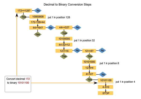
Address Values are Between 0 and 255
Because our representation of addresses is limited to decimal values for a single octet, we will only examine the process of converting 8-bit binary to the decimal values of 0 to 255. To begin the conversion process, we start by determining if the decimal number is equal to or greater than our largest decimal value represented by the most-significant bit. In the highest position, we determine if the value is equal to or greater than 128. If the value is smaller than 128, we place a 0 in the 128-bit position and move to the 64-bit position. If the value in the 128-bit position is larger than or equal to 128, we place a 1 in the 128 position and subtract 128 from the number being converted. We then compare the remainder of this operation to the next smaller value, 64. We continue this process for all the remaining bit positions.
Addresses for Different Purposes
Types of Addresses in an IPv4 Network
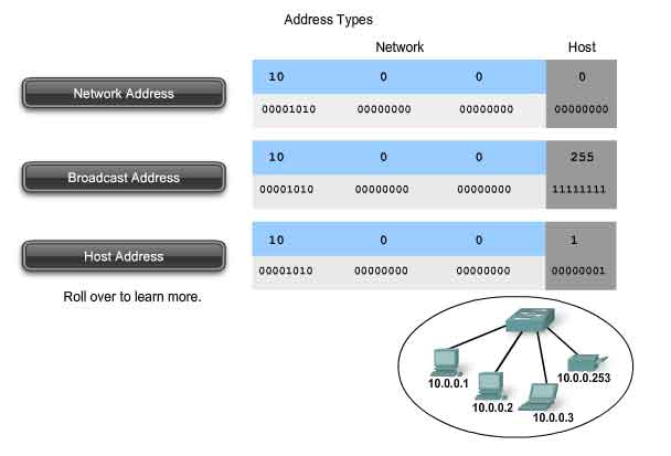
Within the address range of each IPv4 network, we have three types of addresses:
Network address - The address by which we refer to the network
Broadcast address - A special address used to send data to all hosts in the network
Host addresses - The addresses assigned to the end devices in the network
Network Address
The network address is a standard way to refer to a network. For example, we could refer to the network shown in the figure as "the 10.0.0.0 network." This is a much more convenient and descriptive way to refer to the network than using a term like "the first network." All hosts in the 10.0.0.0 network will have the same network bits.
Within the IPv4 address range of a network, the lowest address is reserved for the network address. This address has a 0 for each host bit in the host portion of the address.
Broadcast Address
The IPv4 broadcast address is a special address for each network that allows communication to all the hosts in that network. To send data to all hosts in a network, a host can send a single packet that is addressed to the broadcast address of the network.
The broadcast address uses the highest address in the network range. This is the address in which the bits in the host portion are all 1s. For the network 10.0.0.0 with 24 network bits, the broadcast address would be 10.0.0.255. This address is also referred to as the directed broadcast.
Host Addresses
As described previously, every end device requires a unique address to deliver a packet to that host. In IPv4 addresses, we assign the values between the network address and the broadcast address to the devices in that network.
Network Prefixes
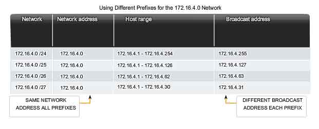
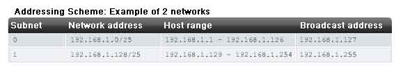
An important question is: How do we know how many bits represent the network portion and how many bits represent the host portion? When we express an IPv4 network address, we add a prefix length to the network address. The prefix length is the number of bits in the address that gives us the network portion. For example, in 172.16.4.0 /24, the /24 is the prefix length - it tells us that the first 24 bits are the network address. This leaves the remaining 8 bits, the last octet, as the host portion. Later in this chapter, we will learn more about another entity that is used to specify the network portion of an IPv4 address to the network devices. It is called the subnet mask. The subnet mask consists of 32 bits, just as the address does, and uses 1s and 0s to indicate which bits of the address are network bits and which bits are host bits. Networks are not always assigned a /24 prefix. Depending on the number of hosts on the network, the prefix assigned may be different. Having a different prefix number changes the host range and broadcast address for each network. Notice that the network address could remain the same, but the host range and the broadcast address are different for the different prefix lengths. In this figure you can also see that the number of hosts that can be addressed on the network changes as well.
Calculating Network, Hosts and Broadcast Addresses
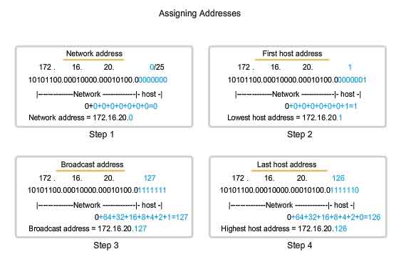
At this point, you may be wondering: How do we calculate these addresses? This calculation process requires us to look at these addresses in binary. In the example network divisions, we need to look at the octet of the address where the prefix divides the network portion from the host portion. In all of these examples, it is the last octet. While this is common, the prefix can also divide any of the octets. To get started understanding this process of determining the address assignments, let's break some examples down into binary. In the first box, we see the representation of the network address. With a 25 bit prefix, the last 7 bits are host bits. To represent the network address, all of these host bits are '0'. This makes the last octet of the address 0. This makes the network address 172.16.20.0 /25. In the second box, we see the calculation of the lowest host address. This is always one greater than the network address. In this case, the last of the seven host bits becomes a '1'. With the lowest bit of host address set to a 1, the lowest host address is 172.16.20.1. The third box shows the calculation of the broadcast address of the network. Therefore, all seven host bits used in this network are all '1s'. From the calculation, we get 127 in the last octet. This gives us a broadcast address of 172.16.20.127. The fourth box presents the calculation of the highest host address. The highest host address for a network is always one less than the broadcast. This means the lowest host bit is a '0' and all other host bits as '1s'. As seen, this makes the highest host address in this network 172.16.20.126. Although for this example we expanded all of the octets, we only need to examine the content of the divided octet.
Unicast, Broadcast, Multicast - Types of Communication
In an IPv4 network, the hosts can communicate one of three different ways:
Unicast - the process of sending a packet from one host to an individual host
Broadcast - the process of sending a packet from one host to all hosts in the network
Multicast - the process of sending a packet from one host to a selected group of hosts
These three types of communication are used for different purposes in the data networks. In all three cases, the IPv4 address of the originating host is placed in the packet header as the source address.
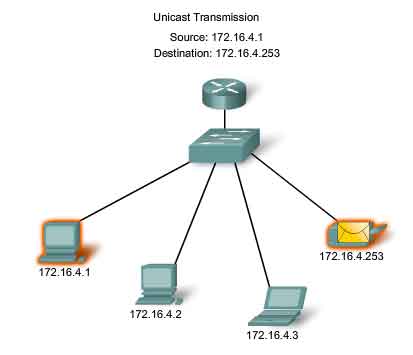
Unicast Traffic
Unicast communication is used for the normal host-to-host communication in both a client/server and a peer-to-peer network. Unicast packets use the host address of the destination device as the destination address and can be routed through an internetwork. Broadcast and multicast, however, use special addresses as the destination address. Using these special addresses, broadcasts are generally restricted to the local network. The scope of multicast traffic also may be limited to the local network or routed through an internetwork. In an IPv4 network, the unicast address applied to an end device is referred to as the host address. For unicast communication, the host addresses assigned to the two end devices are used as the source and destination IPv4 addresses. During the encapsulation process, the source host places its IPv4 address in the unicast packet header as the source host address and the IPv4 address of the destination host in the packet header as the destination address. The communication using a unicast packet can be forwarded through an internetwork using the same addresses.
Broadcast Transmission
Because broadcast traffic is used to send packets to all hosts in the network, a packet uses a special broadcast address. When a host receives a packet with the broadcast address as the destination, it processes the packet as it would a packet to its unicast address. Broadcast transmission is used for the location of special services/devices for which the address is not known or when a host needs to provide information to all the hosts on the network. Some examples for using broadcast transmission are:
Mapping upper layer addresses to lower layer addresses
Requesting an address
Exchanging routing information by routing protocols
When a host needs information, the host sends a request, called a query, to the broadcast address. All hosts in the network receive and process this query. One or more of the hosts with the requested information will respond, typically using unicast. Similarly, when a host needs to send information to the hosts on a network, it creates and sends a broadcast packet with the information. Unlike unicast, where the packets can be routed throughout the internetwork, broadcast packets are usually restricted to the local network. This restriction is dependent on the configuration of the router that borders the network and the type of broadcast. There are two types of broadcasts: directed broadcast and limited broadcast.
Directed Broadcast
A directed broadcast is sent to all hosts on a specific network. This type of broadcast is useful for sending a broadcast to all hosts on a non-local network. For example, for a host outside of the network to communicate with the hosts within the 172.16.4.0 /24 network, the destination address of the packet would be 172.16.4.255. This is shown in the figure. Although routers do not forward directed broadcasts by default, they may be configured to do so.
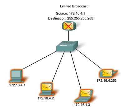
Limited Broadcast
The limited broadcast is used for communication that is limited to the hosts on the local network. These packets use a destination IPv4 address 255.255.255.255. Routers do not forward this broadcast. Packets addressed to the limited broadcast address will only appear on the local network. For this reason, an IPv4 network is also referred to as a broadcast domain. Routers form the boundary for a broadcast domain.
As an example, a host within the 172.16.4.0 /24 network would broadcast to all the hosts in its network using a packet with a destination address of 255.255.255.255.
As you learned earlier, when a packet is broadcast, it uses resources on the network and also forces every host on the network that receives it to process the packet. Therefore, broadcast traffic should be limited so that it does not adversely affect performance of the network or devices. Because routers separate broadcast domains, subdividing networks with excessive broadcast traffic can improve network performance.
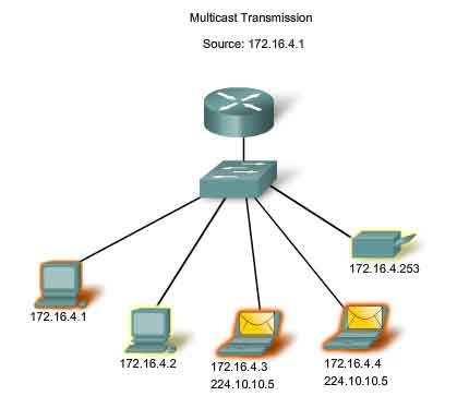
Multicast Transmission
Multicast transmission is designed to conserve the bandwidth of the IPv4 network. It reduces traffic by allowing a host to send a single packet to a selected set of hosts. To reach multiple destination hosts using unicast communication, a source host would need to send an individual packet addressed to each host. With multicast, the source host can send a single packet that can reach thousands of destination hosts.
Some examples of multicast transmission are:
Video and audio distribution
Routing information exchange by routing protocols
Distribution of software
News feeds
Multicast Clients
Hosts that wish to receive particular multicast data are called multicast clients. The multicast clients use services initiated by a client program to subscribe to the multicast group. Each multicast group is represented by a single IPv4 multicast destination address. When an IPv4 host subscribes to a multicast group, the host processes packets addressed to this multicast address as well as packets addressed to its uniquely allocated unicast address. As we will see, IPv4 has set aside a special block of addresses from 224.0.0.0 to 239.255.255.255 for multicast groups addressing.
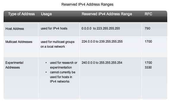
Reserved IPv4 Address Ranges
Expressed in dotted decimal format, the IPv4 address range is 0.0.0.0 to 255.255.255.255. As you have already seen, not all of these addresses can be used as host addresses for unicast communication.
Experimental Addresses
One major block of addresses reserved for special purposes is the IPv4 experimental address range 240.0.0.0 to 255.255.255.254. Currently, these addresses are listed as reserved for future use (RFC 3330). This suggests that they could be converted to usable addresses. Currently, they cannot be used in IPv4 networks. However, these addresses could be used for research or experimentation.
Multicast Addresses
As previously shown, another major block of addresses reserved for special purposes is the IPv4 multicast address range 224.0.0.0 to 239.255.255.255. Additionally, the multicast address range is subdivided into different types of addresses: reserved link local addresses and globally scoped addresses. One additional type of multicast address is the administratively scoped addresses, also called limited scope addresses. The IPv4 multicast addresses 224.0.0.0 to 224.0.0.255 are reserved link local addresses. These addresses are to be used for multicast groups on a local network. Packets to these destinations are always transmitted with a time-to-live (TTL) value of 1. Therefore, a router connected to the local network should never forward them. A typical use of reserved link-local addresses is in routing protocols using multicast transmission to exchange routing information. The globally scoped addresses are 224.0.1.0 to 238.255.255.255. They may be used to multicast data across the Internet. For example, 224.0.1.1 has been reserved for Network Time Protocol (NTP) to synchronize the time-of-day clocks of network devices.
Host Addresses
After accounting for the ranges reserved for experimental addresses and multicast addresses, this leaves an address range of 0.0.0.0 to 223.255.255.255 that could be used for IPv4 hosts. However, within this range are many addresses that are already reserved for special purposes. Although we have previously covered some of these addresses, the major reserved addresses are discussed in the next section.
Public and Private Addresses
Although most IPv4 host addresses are public addresses designated for use in networks that are accessible on the Internet, there are blocks of addresses that are used in networks that require limited or no Internet access. These addresses are called private addresses.
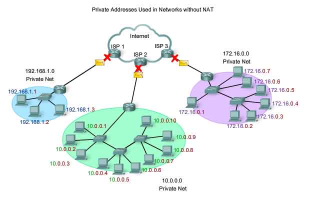
Private Addresses
The private address blocks are:
10.0.0.0 to 10.255.255.255 (10.0.0.0 /8)
172.16.0.0 to 172.31.255.255 (172.16.0.0 /12)
192.168.0.0 to 192.168.255.255 (192.168.0.0 /16)
Private space address blocks, as shown in the figure, are set aside for use in private networks. The use of these addresses need not be unique among outside networks. Hosts that do not require access to the Internet at large may make unrestricted use of private addresses. However, the internal networks still must design network address schemes to ensure that the hosts in the private networks use IP addresses that are unique within their networking environment. Many hosts in different networks may use the same private space addresses. Packets using these addresses as the source or destination should not appear on the public Internet. The router or firewall device at the perimeter of these private networks must block or translate these addresses. Even if these packets were to make their way to the Internet, the routers would not have routes to forward them to the appropriate private network.
Network Address Translation (NAT)
With services to translate private addresses to public addresses, hosts on a privately addressed network can have access to resources across the Internet. These services, called Network Address Translation (NAT), can be implemented on a device at the edge of the private network. NAT allows the hosts in the network to "borrow" a public address for communicating to outside networks. While there are some limitations and performance issues with NAT, clients for most applications can access services over the Internet without noticeable problems.
Public Addresses
The vast majority of the addresses in the IPv4 unicast host range are public addresses. These addresses are designed to be used in the hosts that are publicly accessible from the Internet. Even within these address blocks, there are many addresses that are designated for other special purposes.
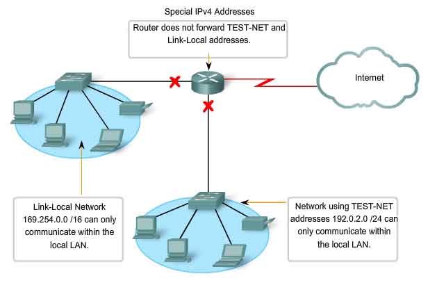
Special IPv4 Addresses
There are certain addresses that cannot be assigned to hosts for various reasons. There are also special addresses that can be assigned to hosts but with restrictions on how those hosts can interact within the network.
Network and Broadcast Addresses
As explained earlier, within each network the first and last addresses cannot be assigned to hosts. These are the network address and the broadcast address, respectively.
Default Route
Also presented earlier, we represent the IPv4 default route as 0.0.0.0. The default route is used as a "catch all" route when a more specific route is not available. The use of this address also reserves all addresses in the 0.0.0.0 - 0.255.255.255 (0.0.0.0 /8) address block.
Loopback
One such reserved address is the IPv4 loopback address 127.0.0.1. The loopback is a special address that hosts use to direct traffic to themselves. The loopback address creates a shortcut method for TCP/IP applications and services that run on the same device to communicate with one another. By using the loopback address instead of the assigned IPv4 host address, two services on the same host can bypass the lower layers of the TCP/IP stack. You can also ping the loopback address to test the configuration of TCP/IP on the local host.
Although only the single 127.0.0.1 address is used, addresses 127.0.0.0 to 127.255.255.255 are reserved. Any address within this block will loop back within the local host. No address within this block should ever appear on any network.
Link-Local Addresses
IPv4 addresses in the address block 169.254.0.0 to 169.254.255.255 (169.254.0.0 /16) are designated as link-local addresses. These addresses can be automatically assigned to the local host by the operating system in environments where no IP configuration is available. These might be used in a small peer-to-peer network or for a host that could not automatically obtain an address from a Dynamic Host Configuration Protocol (DHCP) server. Communication using IPv4 link-local addresses is only suitable for communication with other devices connected to the same network, as shown in the figure. A host must not send a packet with an IPv4 link-local destination address to any router for forwarding and should set the IPv4 TTL for these packets to 1. Link-local addresses do not provide services outside of the local network. However, many client/server and peer-to-peer applications will work properly with IPv4 link-local addresses.
TEST-NET Addresses
The address block 192.0.2.0 to 192.0.2.255 (192.0.2.0 /24) is set aside for teaching and learning purposes. These addresses can be used in documentation and network examples. Unlike the experimental addresses, network devices will accept these addresses in their configurations. You may often find these addresses used with the domain names example.com or example.net in RFCs, vendor, and protocol documentation. Addresses within this block should not appear on the Internet.
Links:
Local-Link addresses http://www.ietf.org/rfc/rfc3927.txt?number=3927
Special-Use IPv4 Addresses http://www.ietf.org/rfc/rfc3330.txt?number=3330
Multicast allocation: http://www.iana.org/assignments/multicast-addresses
Legacy IPv4 Addressing
Historic Network Classes
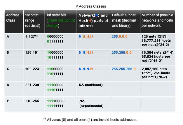
Historically, RFC1700 grouped the unicast ranges into specific sizes called class A, class B, and class C addresses. It also defined class D (multicast) and class E (experimental) addresses, as previously presented. The unicast address classes A, B, and C defined specifically-sized networks as well as specific address blocks for these networks, as shown in the figure. A company or organization was assigned an entire class A, class B, or class C address block. This use of address space is referred to as classful addressing.
Class A Blocks
A class A address block was designed to support extremely large networks with more than 16 million host addresses. Class A IPv4 addresses used a fixed /8 prefix with the first octet to indicate the network address. The remaining three octets were used for host addresses. To reserve address space for the remaining address classes, all class A addresses required that the most significant bit of the high-order octet be a zero. This meant that there were only 128 possible class A networks, 0.0.0.0 /8 to 127.0.0.0 /8, before taking out the reserved address blocks. Even though the class A addresses reserved one-half of the address space, because of their limit of 128 networks, they could only be allocated to approximately 120 companies or organizations.
Class B Blocks
Class B address space was designed to support the needs of moderate to large size networks with more than 65,000 hosts. A class B IP address used the two high-order octets to indicate the network address. The other two octets specified host addresses. As with class A, address space for the remaining address classes needed to be reserved. For class B addresses, the most significant two bits of the high-order octet were 10. This restricted the address block for class B to 128.0.0.0 /16 to 191.255.0.0 /16. Class B had slightly more efficient allocation of addresses than class A because it equally divided 25% of the total IPv4 address space among approximately 16,000 networks.
Class C Blocks
The class C address space was the most commonly available of the historic address classes. This address space was intended to provide addresses for small networks with a maximum of 254 hosts. Class C address blocks used a /24 prefix. This meant that a class C network used only the last octet as host addresses with the three high-order octets used to indicate the network address. Class C address blocks set aside address space for class D (multicast) and class E (experimental) by using a fixed value of 110 for the three most significant bits of the high-order octet. This restricted the address block for class C to 192.0.0.0 /16 to 223.255.255.0 /16. Although it occupied only 12.5% of the total IPv4 address space, it could provide addresses to 2 million networks.
Limits to the Class-based System
Not all organizations' requirements fit well into one of these three classes. Classful allocation of address space often wasted many addresses, which exhausted the availability of IPv4 addresses. For example, a company that had a network with 260 hosts would need to be given a class B address with more than 65,000 addresses. Even though this classful system was all but abandoned in the late 1990s, you will see remnants of it in networks today. For example, when you assign an IPv4 address to a computer, the operating system examines the address being assigned to determine if this address is a class A, class B, or class C. The operating system then assumes the prefix used by that class and makes the appropriate subnet mask assignment. Another example is the assumption of the mask by some routing protocols. When some routing protocols receive an advertised route, it may assume the prefix length based on the class of the address.
Classless Addressing
The system that we currently use is referred to as classless addressing. With the classless system, address blocks appropriate to the number of hosts are assigned to companies or organizations without regard to the unicast class.
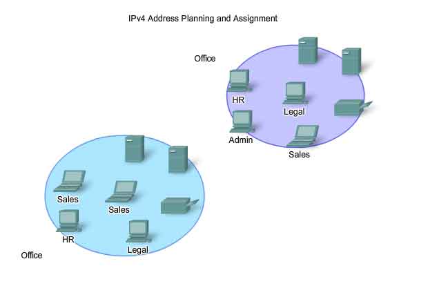
Assigning Addresses
Planning to Address the Network
The allocation of Network layer address space within the corporate network needs to be well designed. Network administrators should not randomly select the addresses used in their networks. Nor should address assignment within the network be random. The allocation of these addresses inside the networks should be planned and documented for the purpose of:
Preventing duplication of addresses
-
Providing and controlling access
- Monitoring security and performance
- Preventing Duplication of Addresses
As you already know, each host in an internetwork must have a unique address. Without the proper planning and documentation of these network allocations, we could easily assign an address to more than one host.
Providing and Controlling Access
Some hosts provide resources to the internal network as well as to the external network. One example of these devices is servers. Access to these resources can be controlled by the Layer 3 address. If the addresses for these resources are not planned and documented, the security and accessibility of the devices are not easily controlled. For example, if a server has a random address assigned, blocking access to its address is difficult and clients may not be able to locate this resource.
Monitoring Security and Performance
Similarly, we need to monitor the security and performance of the network hosts and the network as a whole. As part of the monitoring process, we examine network traffic looking for addresses that are generating or receiving excessive packets. If we have proper planning and documentation of the network addressing, we can identify the device on the network that has a problematic address.
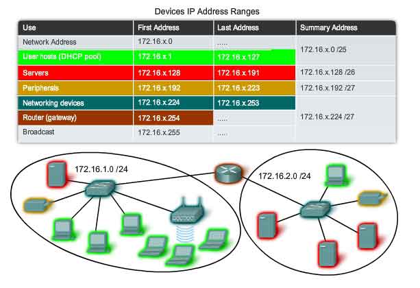
Assigning Addresses within a Network
As you have already learned, hosts are associated with an IPv4 network by a common network portion of the address. Within a network, there are different types of hosts. Some examples of different types of hosts are:
-
End devices for users
- Servers and peripherals
- Hosts that are accessible from the Internet
- Intermediary devices
Each of these different device types should be allocated to a logical block of addresses within the address range of the network.
An important part of planning an IPv4 addressing scheme is deciding when private addresses are to be used and where they are to be applied.
Considerations include:
-
Will there be more devices connected to the network than public addresses allocated by the network's ISP?
- Will the devices need to be accessed from outside the local network?
- If devices that may be assigned private addresses require access to the Internet, is the network capable of providing a Network Address Translation (NAT) service?
If there are more devices than available public addresses, only those devices that will directly access the Internet - such as web servers - require a public address. A NAT service would allow those devices with private addresses to effectively share the remaining public addresses.
Static or Dynamic Addressing for End User Devices
Addresses for User Devices
In most data networks, the largest population of hosts includes the end devices such as PCs, IP phones, printers, and PDAs. Because this population represents the largest number of devices within a network, the largest number of addresses should be allocated to these hosts.
IP addresses can be assigned either statically or dynamically.
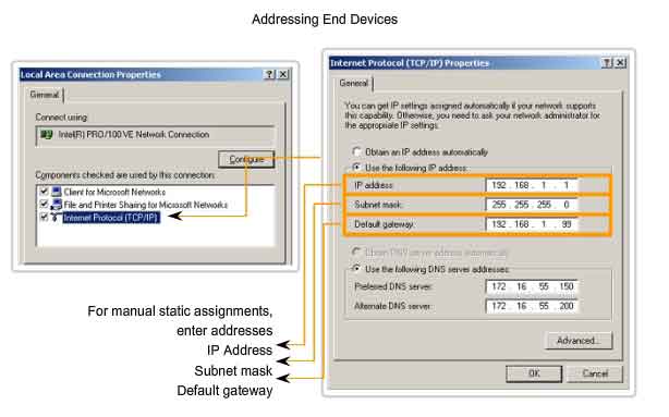
Static Assignment of Addresses
With a static assignment, the network administrator must manually configure the network information for a host, as shown in the figure. At a minimum, this includes entering the host IP address, subnet mask, and default gateway. Static addresses have some advantages over dynamic addresses. For instance, they are useful for printers, servers, and other networking devices that need to be accessible to clients on the network. If hosts normally access a server at a particular IP address, it would cause problems if that address changed. Additionally, static assignment of addressing information can provide increased control of network resources. However, it can be time-consuming to enter the information on each host. When using static IP addressing, it is necessary to maintain an accurate list of the IP address assigned to each device. These are permanent addresses and are not normally reused.
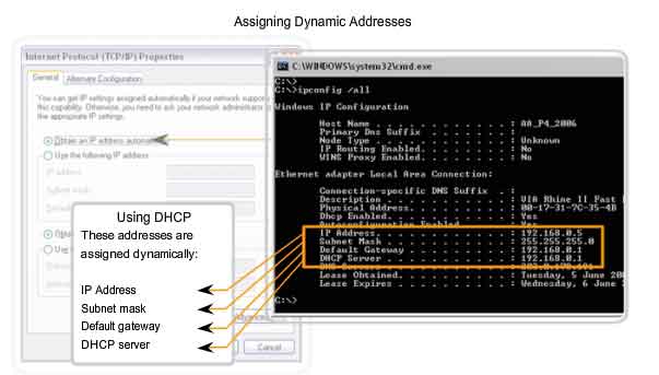
Dynamic Assignment of Addresses
Because of the challenges associated with static address management, end user devices often have addresses dynamically assigned, using Dynamic Host Configuration Protocol (DHCP), as shown in the figure.
DHCP enables the automatic assignment of addressing information such as IP address, subnet mask, default gateway, and other configuration information. The configuration of the DHCP server requires that a block of addresses, called an address pool, be defined to be assigned to the DHCP clients on a network. Addresses assigned to this pool should be planned so that they exclude any addresses used for the other types of devices.
DHCP is generally the preferred method of assigning IP addresses to hosts on large networks because it reduces the burden on network support staff and virtually eliminates entry errors.
Another benefit of DHCP is that an address is not permanently assigned to a host but is only "leased" for a period of time. If the host is powered down or taken off the network, the address is returned to the pool for reuse. This feature is especially helpful for mobile users that come and go on a network.
Assigning Addresses to Other Devices
Addresses for Servers and Peripherals
Any network resource such as a server or a printer should have a static IPv4 address, as shown in the figure. The client hosts access these resources using the IPv4 addresses of these devices. Therefore, predictable addresses for each of these servers and peripherals are necessary. Servers and peripherals are a concentration point for network traffic. There are many packets sent to and from the IPv4 addresses of these devices. When monitoring network traffic with a tool like Wireshark, a network administrator should be able to rapidly identify these devices. Using a consistent numbering system for these devices makes the identification easier.
Addresses for Hosts that are Accessible from Internet
In most internetworks, only a few devices are accessible by hosts outside of the corporation. For the most part, these devices are usually servers of some type. As with all devices in a network that provide network resources, the IPv4 addresses for these devices should be static. In the case of servers accessible by the Internet, each of these must have a public space address associated with it. Additionally, variations in the address of one of these devices will make this device inaccessible from the Internet. In many cases, these devices are on a network that is numbered using private addresses. This means that the router or firewall at the perimeter of the network must be configured to translate the internal address of the server into a public address. Because of this additional configuration in the perimeter intermediary device, it is even more important that these devices have a predictable address.
Addresses for Intermediary Devices
Intermediary devices are also a concentration point for network traffic. Almost all traffic within or between networks passes through some form of intermediary device. Therefore, these network devices provide an opportune location for network management, monitoring, and security.
Most intermediary devices are assigned Layer 3 addresses. Either for the device management or for their operation. Devices such as hubs, switches, and wireless access points do not require IPv4 addresses to operate as intermediary devices. However, if we need to access these devices as hosts to configure, monitor, or troubleshoot network operation, they need to have addresses assigned. Because we need to know how to communicate with intermediary devices, they should have predictable addresses. Therefore, their addresses are typically assigned manually. Additionally, the addresses of these devices should be in a different range within the network block than user device addresses.
Routers and Firewalls
Unlike the other intermediary devices mentioned, routers and firewall devices have an IPv4 address assigned to each interface. Each interface is in a different network and serves as the gateway for the hosts in that network. Typically, the router interface uses either the lowest or highest address in the network. This assignment should be uniform across all networks in the corporation so that network personnel will always know the gateway of the network no matter which network they are working on. Router and firewall interfaces are the concentration point for traffic entering and leaving the network. Because the hosts in each network use a router or firewall device interface as the gateway out of the network, many packets flow through these interfaces. Therefore, these devices can play a major role in network security by filtering packets based on source and/or destination IPv4 addresses. Grouping the different types of devices into logical addressing groups makes the assignment and operation of this packet filtering more efficient.
Who Assigns the Different Addresses?
A company or organization that wishes to have network hosts accessible from the Internet must have a block of public addresses assigned. The use of these public addresses is regulated and the company or organization must have a block of addresses allocated to it. This is true for IPv4, IPv6, and multicast addresses. Internet Assigned Numbers Authority (IANA) (http://www.iana.net) is the master holder of the IP addresses. The IP multicast addresses and the IPv6 addresses are obtained directly from IANA. Until the mid-1990s, all IPv4 address space was managed directly by the IANA. At that time, the remaining IPv4 address space was allocated to various other registries to manage for particular purposes or for regional areas. These registration companies are called Regional Internet Registries (RIRs), as shown in the figure.
The major registries are:
-
AfriNIC (African Network Information Centre) - Africa Region http://www.afrinic.net
- APNIC (Asia Pacific Network Information Centre) - Asia/Pacific Region http://www.apnic.net
- ARIN (American Registry for Internet Numbers) - North America Region http://www.arin.net
- LACNIC (Regional Latin-American and Caribbean IP Address Registry) - Latin America and some Caribbean Islands http://www.lacnic.net
- RIPE NCC (Reseaux IP Europeans) - Europe, the Middle East, and Central Asia http://www.ripe.net
Links:
IPv4 address registries allocations:
http://www.ietf.org/rfc/rfc1466.txt?number=1466
http://www.ietf.org/rfc/rfc2050.txt?number=2050
IPV4 Addresses allocation: http://www.iana.org/ipaddress/ip-addresses.htm
IP Addressing lookup: http://www.arin.net/whois/
The Role of the ISP
Most companies or organizations obtain their IPv4 address blocks from an ISP. An ISP will generally supply a small number of usable IPv4 addresses (6 or 14) to their customers as a part of their services. Larger blocks of addresses can be obtained based on justification of needs and for additional service costs. In a sense, the ISP loans or rents these addresses to the organization. If we choose to move our Internet connectivity to another ISP, the new ISP will provide us with addresses from the address blocks that have been provided to them, and our previous ISP returns the blocks loaned to us to their allocation to be loaned to another customer.
ISP Services
To get access to the services of the Internet, we have to connect our data network to the Internet using an Internet Service Provider (ISP).
ISPs have their own set of internal data networks to manage Internet connectivity and to provide related services. Among the other services that an ISP generally provides to its customers are DNS services, e-mail services, and a website. Depending on the level of service required and available, customers use different tiers of an ISP.
ISP Tiers
ISPs are designated by a hierarchy based on their level of connectivity to the Internet backbone. Each lower tier obtains connectivity to the backbone via a connection to a higher tier ISP, as shown in the figure.
Tier 1
At the top of the ISP hierarchy are Tier 1 ISPs. These ISPs are large national or international ISPs that are directly connected to the Internet backbone. The customers of Tier 1 ISPs are either lower-tiered ISPs or large companies and organizations. Because they are at the top of Internet connectivity, they engineer highly reliable connections and services. Among the technologies used to support this reliability are multiple connections to the Internet backbone. The primary advantages for customers of Tier 1 ISPs are reliability and speed. Because these customers are only one connection away from the Internet, there are fewer opportunities for failures or traffic bottlenecks. The drawback for Tier 1 ISP customers is its high cost.
Tier 2
Tier 2 ISPs acquire their Internet service from Tier 1 ISPs. Tier 2 ISPs generally focus on business customers. Tier 2 ISPs usually offer more services than the other two tiers of ISPs. These tier 2 ISPs tend to have the IT resources to operate their own services such as DNS, e-mail servers, and web servers. Other services that Tier 2 ISPs may offer include website development and maintenance, e-commerce/e-business, and VoIP. The primary disadvantage of Tier 2 ISPs, as compared to Tier 1 ISPs, is slower Internet access. Because Tier 2 ISPs are at least one more connection away from the Internet backbone, they also tend to have lower reliability than Tier 1 ISPs.
Tier 3
Tier 3 ISPs purchase their Internet service from Tier 2 ISPs. The focus of these ISPs is the retail and home markets in a specific locale. Tier 3 customers typically do not need many of the services required by Tier 2 customers. Their primary need is connectivity and support. These customers often have little or no computer or network expertise. Tier 3 ISPs often bundle Internet connectivity as a part of network and computer service contracts for their customers. While they may have reduced bandwidth and less reliability than Tier 1 and Tier 2 providers, they are often good choices for small to medium size companies.
Overview of IPv6
In the early 1990s, the Internet Engineering Task Force (IETF) grew concerned about the exhaustion of the IPv4 network addresses and began to look for a replacement for this protocol. This activity led to the development of what is now known as IPv6. Creating expanded addressing capabilities was the initial motivation for developing this new protocol. Other issues were also considered during the development of IPv6, such as:
-
Improved packet handling
- Increased scalability and longevity
- QoS mechanisms
- Integrated security
To provide these features, IPv6 offers:
-
128-bit hierarchical addressing - to expand addressing capabilities
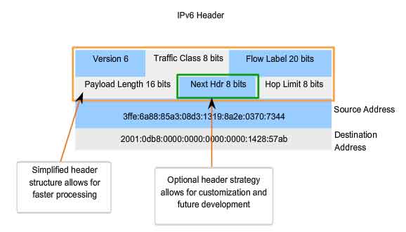
- Header format simplification - to improve packet handling
- Improved support for extensions and options - for increased scalability/longevity and improved packet handling
- Flow labeling capability - as QoS mechanisms
- Authentication and privacy capabilities - to integrate security
IPv6 is not merely a new Layer 3 protocol - it is a new protocol suite. New protocols at various layers of the stack have been developed to support this new protocol. There is a new messaging protocol (ICMPv6) and new routing protocols. Because of the increased size of the IPv6 header, it also impacts the underlying network infrastructure.
Transition to IPv6
As you can see from this brief introduction, IPv6 has been designed with scalability to allow for years of internetwork growth. However, IPv6 is being implemented slowly and in select networks. Because of better tools, technologies, and address management in the last few years, IPv4 is still very widely used, and likely to remain so for some time into the future. However, IPv6 may eventually replace IPv4 as the dominant Internet protocol.
Links:
IPv6: http://www.ietf.org/rfc/rfc2460.txt?number=2460
IPv6 addressing: http://www.ietf.org/rfc/rfc3513.txt?number=3513
IPv6 security: http://www.ietf.org/rfc/rfc2401.txt?number=2401
IPv6 security: http://www.ietf.org/rfc/rfc3168.txt?number=3168
IPv6 security: http://www.ietf.org/rfc/rfc4302.txt?number=4302
ICMPv6: http://www.ietf.org/rfc/rfc4443.txt?number=4443
Is It On My Network?
The Subnet Mask - Defining the Network and Host Portions
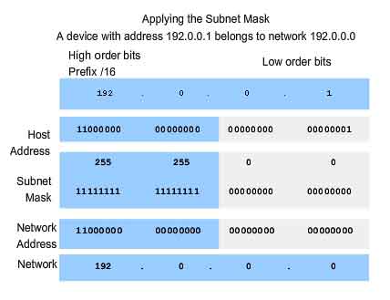
As we learned earlier, an IPv4 address has a network portion and a host portion. We referred to the prefix length as the number of bits in the address giving us the network portion. The prefix is a way to define the network portion that is human readable. The data network must also have this network portion of the addresses defined. To define the network and host portions of an address, the devices use a separate 32-bit pattern called a subnet mask, as shown in the figure. We express the subnet mask in the same dotted decimal format as the IPv4 address. The subnet mask is created by placing a binary 1 in each bit position that represents the network portion and placing a binary 0 in each bit position that represents the host portion. The prefix and the subnet mask are different ways of representing the same thing - the network portion of an address.
As shown in the figure, a /24 prefix is expressed as a subnet mask as 255.255.255.0 (11111111.11111111.11111111.00000000). The remaining bits (low order) of the subnet mask are zeroes, indicating the host address within the network. The subnet mask is configured on a host in conjunction with the IPv4 address to define the network portion of that address.
For example, let's look at the host 172.16.4.35/27:
address
172.16.20.35
10101100.00010000.00010100.00100011
subnet mask
255.255.255.224
11111111.11111111.11111111.11100000
network address
172.16.20.32
10101100.00010000.00010100.00100000
Because the high order bits of the subnet masks are contiguous 1s, there are only a limited number of subnet values within an octet. You will recall that we only need to expand an octet if the network and host division falls within that octet. Therefore, there are a limited number 8 bit patterns used in address masks.
These patterns are:
00000000 = 0
10000000 = 128
11000000 = 192
11100000 = 224
11110000 = 240
11111000 = 248
11111100 = 252
11111110 = 254
11111111 = 255
If the subnet mask for an octet is represented by 255, then all the equivalent bits in that octet of the address are network bits. Similarly, if the subnet mask for an octet is represented by 0, then all the equivalent bits in that octet of the address are host bits. In each of these cases, it is not necessary to expand this octet to binary to determine the network and host portions.
ANDing - What Is In Our Network?
Inside data network devices, digital logic is applied for their interpretation of the addresses. When an IPv4 packet is created or forwarded, the destination network address must be extracted from the destination address. This is done by a logic called AND. The IPv4 host address is logically ANDed with its subnet mask to determine the network address to which the host is associated. When this ANDing between the address and the subnet mask is performed, the result yields the network address.
The AND Operation
ANDing is one of three basic binary operations used in digital logic. The other two are OR and NOT. While all three are used in data networks, AND is used in determining the network address. Therefore, our discussion here will be limited to logical AND. Logical AND is the comparison of two bits that yields the following results:
1 AND 1 = 1
1 AND 0 = 0
0 AND 1 = 0
0 AND 0 = 0
The result from anything ANDed with a 1 yields a result that is the original bit. That is, 0 AND 1 is 0 and 1 AND 1 is 1. Consequently, anything ANDed with a 0 yields a 0.These properties of ANDing are used with the subnet mask to "mask" the host bits of an IPv4 address. Each bit of the address is ANDed with the corresponding bit of the subnet mask. Because all the bits of the subnet mask that represent host bits are 0s, the host portion of the resulting network address becomes all 0s. Recall that an IPv4 address with all 0s in the host portion represents the network address. Likewise, all the bits of the subnet mask that indicate network portion are 1s. When each of these 1s is ANDed with the corresponding bit of the address, the resulting bits are identical to the original address bits.
Reasons to Use AND
This ANDing between the host address and subnet mask is performed by devices in a data network for various reasons. Routers use ANDing to determine an acceptable route for an incoming packet. The router checks the destination address and attempts to associate this address with a next hop. As a packet arrives at a router, the router performs ANDing on the IP destination address in the incoming packet and with the subnet mask of potential routes. This yields a network address that is compared to the route from the routing table whose subnet mask was used. An originating host must determine if a packet should be sent directly to a host in the local network or be directed to the gateway. To make this determination, a host must first know its own network address. A host extracts its network address by ANDing its address with its subnet mask. A logical AND is also performed by an originating host between the destination address of the packet and the subnet mask of the this host. This yields the network address of the destination. If this network address matches the network address of the local host, the packet is sent directly to the destination host. If the two network addresses do not match, the packet is sent to the gateway.
The Importance of AND
If the routers and end devices calculate these processes without our intervention, why do we need to learn how to AND? The more we understand and are able to predict about the operation of a network, the more equipped we are to design and/or administer one. In network verification/troubleshooting, we often need to determine what IPv4 network a host is on or if two hosts are on the same IP network. We need to make this determination from the perspective of the network devices. Due to improper configuration, a host may see itself on a network that was not the intended one. This can create an operation that seems erratic unless diagnosed by examining the ANDing processes used by the host. Also, a router may have many different routes that can satisfy the forwarding of packet to a given destination. The selection of the route used for any given packet is a complex operation. For example, the prefix forming these routes is not directly associated with the networks assigned to the host. This means that a route in the routing table may represent many networks. If there were issues with routing packets, you would need to determine how the router would make the routing decision. Although there are subnet calculators available, it is helpful for a network administrator to know how to manually calculate subnets.
Calculating Addresses
Basic subnetting
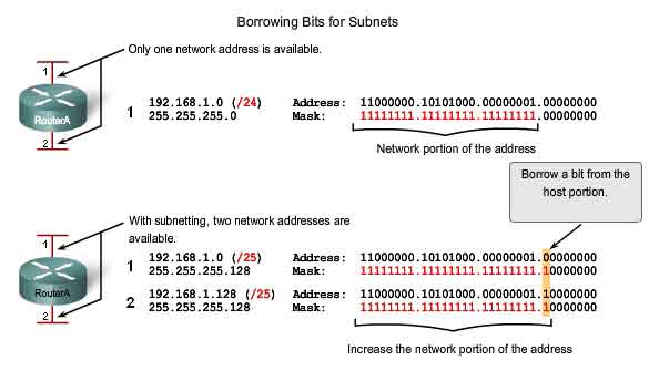
Subnetting allows for creating multiple logical networks from a single address block. Since we use a router to connect these networks together, each interface on a router must have a unique network ID. Every node on that link is on the same network. We create the subnets by using one or more of the host bits as network bits. This is done by extending the mask to borrow some of the bits from the host portion of the address to create additional network bits. The more host bits used, the more subnets that can be defined. For each bit borrowed, we double the number of subnetworks available. For example, if we borrow 1 bit, we can define 2 subnets. If we borrow 2 bits, we can have 4 subnets. However, with each bit we borrow, fewer host addresses are available per subnet. RouterA in the figure has two interfaces to interconnect two networks. Given an address block of 192.168.1.0 /24, we will create two subnets. We borrow one bit from the host portion by using a subnet mask of 255.255.255.128, instead of the original 255.255.255.0 mask. The most significant bit in the last octet is used to distinguish between the two subnets. For one of the subnets, this bit is a "0" and for the other subnet this bit is a "1".
Formula for calculating subnets
Use this formula to calculate the number of subnets:
2^n where n = the number of bits borrowed
In this example, the calculation looks like this:
2^1 = 2 subnets
The number of hosts
To calculate the number of hosts per network, we use the formula of 2^n - 2 where n = the number of bits left for hosts.
Applying this formula, (2^7 - 2 = 126) shows that each of these subnets can have 126 hosts.
For each subnet, examine the last octet in binary. The values in these octets for the two networks are:
Subnet 1: 00000000 = 0
Subnet 2: 10000000 = 128
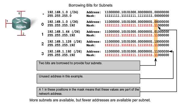
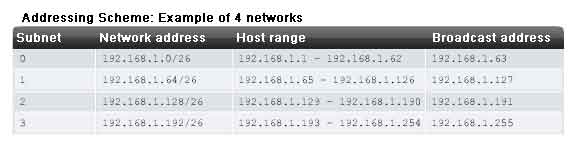
Example with 3 subnets
Next, consider an internetwork that requires three subnets. See the figure.
Again we start with the same 192.168.1.0 /24 address block. Borrowing a single bit would only provide two subnets. To provide more networks, we change the subnet mask to 255.255.255.192 and borrow two bits. This will provide four subnets.
Calculate the subnet with this formula:
2^2 = 4 subnets
The number of hosts
To calculate the number of hosts, begin by examining the last octet. Notice these subnets.
Subnet 0: 0 = 00000000
Subnet 1: 64 = 01000000
Subnet 2: 128 = 10000000
Subnet 3: 192 = 11000000
Apply the host calculation formula.
2^6 - 2 = 62 hosts per subnet
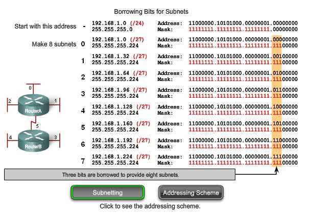
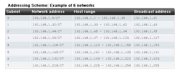
Example with 6 subnets
Consider this example with five LANs and a WAN for a total of 6 networks. See the figure.
To accommodate 6 networks, subnet 192.168.1.0 /24 into address blocks using the formula:
2^3 = 8
To get at least 6 subnets, borrow three host bits. A subnet mask of 255.255.255.224 provides the three additional network bits.
The number of hosts
To calculate the number of hosts, begin by examining the last octet. Notice these subnets.
0 = 00000000
32 = 00100000
64 = 01000000
96 = 01100000
128 = 10000000
160 = 10100000
192 = 11000000
224 = 11100000
Apply the host calculation formula:
2^5 - 2 = 30 hosts per subnet.
Subnetting - Dividing Networks into Right Sizes
Every network within the internetwork of a corporation or organization is designed to accommodate a finite number of hosts. Some networks, such as point-to-point WAN links, only require a maximum of two hosts. Other networks, such as a user LAN in a large building or department, may need to accommodate hundreds of hosts. Network administrators need to devise the internetwork addressing scheme to accommodate the maximum number of hosts for each network. The number of hosts in each division should allow for growth in the number of hosts.
Determine the Total Number of Hosts
First, consider the total number of hosts required by the entire corporate internetwork. We must use a block of addresses that is large enough to accommodate all devices in all the corporate networks. This includes end user devices, servers, intermediate devices, and router interfaces. Consider the example of a corporate internetwork that needs to accommodate 800 hosts in its four locations.
Determine the Number and Size of the Networks
Next, consider the number of networks and the size of each required based on common groupings of hosts. We subnet our network to overcome issues with location, size, and control. In designing the addressing, we consider the factors for grouping the hosts that we discussed previously:
-
Grouping based on common geographic location
- Grouping hosts used for specific purposes
- Grouping based on ownership
Each WAN link is a network. We create subnets for the WAN that interconnect different geographic locations. When connecting the different locations, we use a router to account for the hardware differences between the LANs and the WAN. Although hosts in a common geographic location typically comprise a single block of addresses, we may need to subnet this block to form additional networks at each location. We need to create subnetworks at the different locations that have hosts for common user needs. We may also have other groups of users that require many network resources, or we may have many users that require their own subnetwork. Additionally, we may have subnetworks for special hosts such as servers. Each of these factors needs to be considered in the network count. We also have to consider any special security or administrative ownership needs that require additional networks. One useful tool in this address planning process is a network diagram. A diagram allows us to see the networks and make a more accurate count. To accommodate 800 hosts in the company's four locations, we use binary arithmetic to allocate a /22 block (2^10-2=1022).
Allocating Addresses
Now that we have a count of the networks and the number of hosts for each network, we need to start allocating addresses from our overall block of addresses. This process begins by allocating network addresses for locations of special networks. We start with the locations that require the most hosts and work down to the point-to-point links. This process ensures that large enough blocks of addresses are made available to accommodate the hosts and networks for these locations. When making the divisions and assignment of available subnets, make sure that there are adequately-sized address blocks available for the larger demands. Also, plan carefully to ensure that the address blocks assigned to the subnet do not overlap.
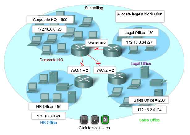
Another helpful tool in this planning process is a spreadsheet. We can place the addresses in columns to visualize the allocation of the addresses.
In our example, we now allocate blocks of addresses to the four locations as well as the WAN links.
With the major blocks allocated, next we subnet any of the locations that require dividing. In our example, we divide the corporate HQ into two networks. This further division of the addresses is often called subnetting the subnets. As with any subnetting, we need to carefully plan the address allocation so that we have available blocks of addresses. The creation of new, smaller networks from a given address block is done by extending the length of the prefix; that is, adding 1s to the subnet mask. Doing this allocates more bits to the network portion of the address to provide more patterns for the new subnet. For each bit we borrow, we double the number of networks we have. For example, if we use 1 bit, we have the potential to divide that block into two smaller networks. With a single bit pattern, we can produce two unique bit patterns, 1 and 0. If we borrow 2 bits, we can provide for 4 unique patterns to represent networks 00, 01, 10, and 11. 3 bits would allow 8 blocks, and so on.
The total Number of Usable Hosts
Recall from the previous section that as we divide the address range into subnets, we lose two host addresses for each new network. These are the network address and broadcast address.
The formula for calculating the number of hosts in a network is:
Usable hosts = 2 n - 2
Where n is the number of bits remaining to be used for hosts.
Links:
Subnet calculator: http://vlsm-calc.net
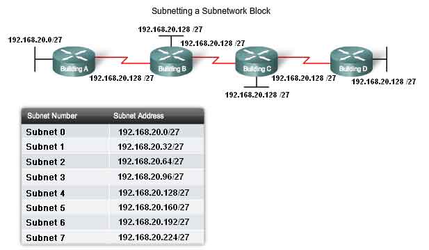
Subnetting - Subnetting a Subnet
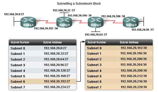
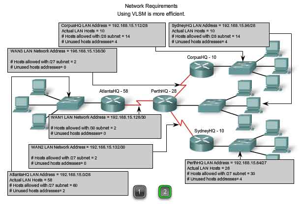
Subnetting a subnet, or using Variable Length Subnet Mask (VLSM) was designed to maximize addressing efficiency. When identifying the total number of hosts using traditional subnetting, we allocate the same number of addresses for each subnet. If all the subnets have the same requirements for the number hosts, these fixed size address blocks would be efficient. However, most often that is not the case. For example, the topology in Figure 1 shows a subnet requirement of seven subnets, one for each of the four LANs and one for each of the three WANs. With the given address of 192.168.20.0, we need to borrow 3 bits from the host bits in the last octet to meet our subnet requirement of seven subnets. These bits are borrowed bits by changing the corresponding subnet mask bits to "1s" to indicate that these bits are now being used as network bits. The last octet of the mask is then represented in binary by 11100000, which is 224. The new mask of 255.255.255.224 is represented with the /27 notation to represent a total of 27 bits for the mask.
In binary this subnet mask is represented as: 11111111.11111111.11111111.11100000
After borrowing three of the host bits to use as network bits, this leaves five host bits. These five bits will allow up to 30 hosts per subnet. Although we have accomplished the task of dividing the network into an adequate number of networks, it was done with a significant waste of unused addresses. For example, only two addresses are needed in each subnet for the WAN links. There are 28 unused addresses in each of the three WAN subnets that have been locked into these address blocks. Further, this limits future growth by reducing the total number of subnets available. This inefficient use of addresses is characteristic of classful addressing. Applying a standard subnetting scheme to scenario is not very efficient and is wasteful. In fact, this example is a good model for showing how subnetting a subnet can be used to maximize address utilization.
Getting More Subnet for Less Hosts
Recall in previous examples we began with the original subnets and gained additional, smaller, subnets to use for the WAN links. By creating smaller subnets, each subnet is able to support 2 hosts, leaving the original subnets free to be allotted to other devices and preventing many addresses from being wasted. To create these smaller subnets for the WAN links, begin with 192.168.20.192. We can divide this subnet into many smaller subnets. To provide address blocks for the WANS with two addresses each, we will borrow three additional host bits to be used as network bits.
Address: 192.168.20.192 In Binary: 11000000.10101000.00010100.11000000
Mask: 255.255.255.252 30 Bits in binary: 11111111.11111111.11111111.11111100
The topology in the figure 2 shows an addressing plan that breaks up the 192.168.20.192 /27 subnets into smaller subnets to provide addresses for the WANs. Doing this reduces the number addresses per subnet to a size appropriate for the WANs. With this addressing, we have subnets 4, 5, and 7 available for future networks, as well as several other subnets available for WANs.
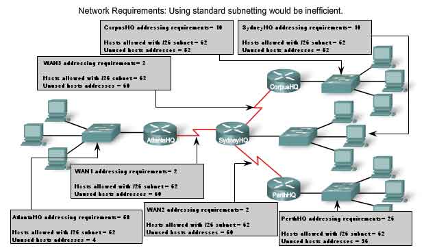
In Figure 1, we will look at addressing from another view. We will consider subnetting based on the number of hosts, including router interfaces and WAN connections. This scenario has the following requirements:
-
AtlantaHQ 58 host addresses
- PerthHQ 26 host addresses
- SydneyHQ 10 host addresses
- CorpusHQ 10 host addresses
- WAN links 2 host addresses (each)
It is clear from these requirements that using a standard subnetting scheme would, indeed, be wasteful. In this internetwork, standard subnetting would lock each subnet into blocks of 62 hosts, which would mean a significant waste of potential addresses. This waste is especially evident in figure 2 where we see that the PerthHQ LAN supports 26 users and the SydneyHQ and CorpusHQ LANs routers support only 10 users each.
Therefore, with the given address block of 192.168.15.0 /24, we will begin designing an addressing scheme to meet the requirements and save potential addresses.
When creating an appropriate addressing scheme, always begin with the largest requirement. In this case, the AtlantaHQ, with 58 users, has the largest requirement. Starting with 192.168.15.0, we will need 6 host bits to accommodate the requirement of 58 hosts, this allows 2 additional bits for the network portion. The prefix for this network would be /26 and a subnet mask of 255.255.255.192.
Let's begin by subnetting the original address block of 192.168.15.0 /24. Using the Usable hosts = 2^n - 2 formula, we calculate that 6 host bits allow 62 hosts in the subnet. The 62 hosts would meet the required 58 hosts of the AtlantaHQ company router.
Address: 192.168.15.0
In Binary: 11000000.10101000.00001111.00000000
Mask: 255.255.255.192
26 Bits in binary: 11111111.11111111.11111111.11000000
The steps for implementing this subnetting scheme are described here.
Assigning the AtlantaHQ LAN
The first step shows a network-planning chart. The second step in the figure shows the entry for the AtlantaHQ. This entry is the results of calculating a subnet from the original 192.168.15.0 /24 block to accommodate the largest LAN, the AtlantaHQ LAN with 58 hosts. Doing this required borrowing an additional 2 host bits, to use a /26 bit mask. By comparison, the following scheme shows how 192.168.15.0 would be subnetted using fixed block addressing to provide large enough address blocks:
Subnet 0: 192.168.15.0 /26 host address range 1 to 62
Subnet 1: 192.168.15.64 /26 host address range 65 to 126
Subnet 2: 192.168.15.128 /26 host address range 129 to 190
Subnet 3: 192.168.15.192 /26 host address range 193 to 254
The fixed blocks would allow only four subnets and therefore not allow enough address blocks for the majority of the subnets in this internetwork. Instead of continuing to use the next available subnet, we need to ensure we make the size of each subnet consistent with the host requirements. Using an addressing scheme directly correlated to the host requirements requires the use of a different method of subnetting.
Assigning the PerthHQ LAN
In the third step, we look at the requirements for the next largest subnet. This is the PerthHQ LAN, requiring 28 host addresses including the router interface. We should begin with next available address of 192.168.15.64 to create an address block for this subnet. By borrowing one more bit, we are able to meet the needs of PerthHQ while limiting the wasted addresses. The borrowed bit gives us a /27 mask with the following address range:
192.168.15.64 /27 host address range 65 to 94
This block of address provides 30 addresses, which meets the requirement of 28 hosts and allows room for growth for this subnet.
Assigning the SydneyHQ LAN and CorpusHQ LAN
See Steps 4 and 5 in the figure.
The fourth and fifth steps provide the addressing for the next largest subnets: SydneyHQ and CorpusHQ LANs. In these two steps, each LAN has the same need for 10 host addresses. This subnetting requires us to borrow another bit, to extend the mask to /28. Starting with address 192.168.15.96, we get the following address blocks:
Subnet 0: 192.168.15.96 /28 host address range 97 to 110
Subnet 1: 192.168.15.112 /28 host address range 113 to 126
These blocks provide 14 addresses for the hosts and router interfaces on each LAN.
Assigning the WANs
See Steps 6, 7, and 8 in the figure.
The last three steps show subnetting for the WAN links. With these point-to-point WAN links only two addresses are required. To meet the requirement, we borrow 2 more bits to use a /30 mask. Using the next available addresses, we get the following address blocks:
Subnet 0: 192.168.15.128 /30 host address range 129 to 130
Subnet 1: 192.168.15.132 /30 host address range 133 to 134
Subnet 2: 192.168.15.136 /30 host address range 137 to 138
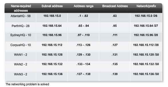
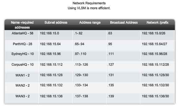
The results shown in our addressing scheme using VLSM displays a wide array of correctly-allocated address blocks. As best practice, we began by documenting our requirements from the largest to the smallest. By starting with the largest requirement, we were able to determine that a fixed block addressing scheme would not allow for efficient use of the IPv4 addresses and, as shown in this example, would not provide enough addresses. From the allocated address block, we borrowed bits to create the address ranges that would fit our topology. Figure 1 shows the assigned ranges. Figure 2 shows the topology with the addressing information.
Using VLSM to allocate the addresses made it possible to apply the subnetting guidelines for grouping hosts based on:
-
Grouping based on common geographic location
- Grouping hosts used for specific purposes
- Grouping based on ownership
In our example, we based the grouping on the number of hosts in a common geographic location.
VLSM Chart
Address planning can also be accomplished using a variety of tools. One method is to use a VLSM chart to identify which blocks of addresses are available for use and which ones are already assigned. This method helps to prevent assigning addresses that have already been allocated. Using the network from our example, we can walk through the address planning using the VLSM chart, to see its use.
The first graphic shows the top portion of the chart. A complete chart for your use is available using the link below. This chart can be used to do address planning for networks with prefixes in the /25 - /30 range. These are the most commonly used network ranges for subnetting. As before, we start with the subnet that has the largest number of hosts. In this case, it is AtlantaHQ with 58 hosts.
Choosing a block for the AtlantaHQ LAN
Following the chart header from left to right, we find the header that indicates a block size of sufficient size for the 58 hosts. This is the /26 column. In this column, we see that there are four blocks of this size:
.0 /26 host address range 1 to 62
.64 /26 host address range 65 to 126
.128 /26 host address range 129 to 190
.192 /26 host address range 193 to 254
Because no addresses have been allocated, we can choose any one of these blocks. Although there might be reasons for using a different block, we commonly use the first available block, the .0 /26. Once we assign the address block, these addresses are considered used. Be sure to mark this block as well as any larger blocks that contain these addresses. By marking these, we can see which address cannot be used and which are still available. Looking at Figure 3, when we allocate the .0 /26 block to the AtlantaHQ, we mark all the blocks that contain these addresses.
Choosing a block for the PerthHQ LAN
Next, we need an address block for the PerthHQ LAN of 26 hosts. Moving across the chart header, we find the column that has the subnets of sufficient size for this LAN. Then we move down the chart to the first available block. In Figure 3, the section of the chart available for PerthHQ is highlighted. The borrowed bit makes the block of addresses available for this LAN. Although we could have chosen any of the available blocks, typically we proceed to the first available block that satisfies the need. The address range for this block is:
.64 /27 host address range 65 to 94
Choosing blocks for the SydneyHQ LAN and the CorpusHQ LAN
As shown in Figure 4, we continue to mark the address blocks to prevent overlapping of address assignment. To meet the needs of the SydneyHQ LAN and CorpusHQ LAN, we again locate the next available blocks. This time we move to the /28 column and move down to the .96 and .112 blocks. Notice that the section of the chart available for SydneyHQ and CorpusHQ is highlighted.
These blocks are:
.96 /28 host address range 97 to 110
.112 /28 host address range 113 to 126
Choosing blocks for the WANs
The last addressing requirement is for the WAN connections between the networks. Looking at Figure 5, we move to the far right column for /30 prefix. We then move down and highlight three available blocks. These blocks will provide the 2 addresses per WAN. These three blocks are:
.128 /30 host address range 129 to 130
.132 /30 host address range 133 to 134
.136 /30 host address range 137 to 138
Looking at Figure 6, the addresses assigned to the WAN are marked to indicate that the blocks containing these can no longer be assigned. Notice with the assignment of these WAN ranges that we have marked several larger blocks that cannot be assigned. These are:
.128 /25
.128 /26
.128 /27
.128 /28
.128 /29
.136 /29
Because these addresses are part of these larger blocks, the assignment of these blocks would overlap the use of these addresses. As we have seen, the usage of VLSM enables us to maximize addressing while minimizing waste. The chart method shown is just one additional tool that network administrators and network technicians can use to create an addressing scheme that is less wasteful than the fixed size block approach.
Testing the Network Layer
Ping 127.0.0.1 - Testing the Local Stack
Ping is a utility for testing IP connectivity between hosts. Ping sends out requests for responses from a specified host address. Ping uses a Layer 3 protocol that is a part on the TCP/IP suite called Internet Control Message Protocol (ICMP). Ping uses an ICMP Echo Request datagram. If the host at the specified address receives the Echo request, it responds with an ICMP Echo Reply datagram. For each packet sent, ping measures the time required for the reply. As each response is received, ping provides a display of the time between the ping being sent and the response received. This is a measure of the network performance. Ping has a timeout value for the response. If a response is not received within that timeout, ping gives up and provides a message indicating that a response was not received. After all the requests are sent, the ping utility provides an output with the summary of the responses. This output includes the success rate and average round-trip time to the destination.
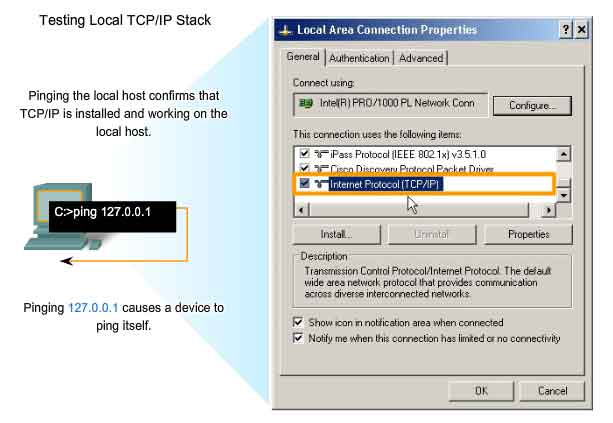
Pinging the Local Loopback
There are some special testing and verification cases for which we can use ping. One case is for testing the internal configuration of IP on the local host. To perform this test, we ping the special reserve address of local loopback (127.0.0.1), as shown in the figure. A response from 127.0.0.1 indicates that IP is properly installed on the host. This response comes from the Network layer. This response is not, however, an indication that the addresses, masks, or gateways are properly configured. Nor does it indicate anything about the status of the lower layer of the network stack. This simply tests IP down through the Network layer of the IP protocol. If we get an error message, it is an indication that TCP/IP is not operational on the host.
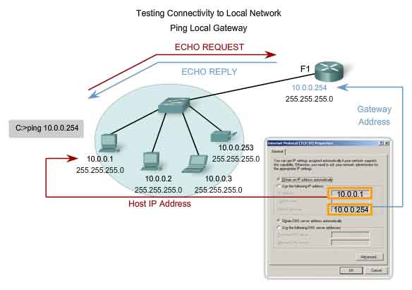
Ping Gateway - Testing Connectivity to the Local LAN
You can also use ping to test the host ability to communicate on the local network. This is generally done by pinging the IP address of the gateway of the host, as shown in the figure. A ping to the gateway indicates that the host and the router's interface serving as that gateway are both operational on the local network. For this test, the gateway address is most often used, because the router is normally always operational. If the gateway address does not respond, you can try the IP address of another host that you are confident is operational in the local network. If either the gateway or another host responds, then the local hosts can successfully communicate over the local network. If the gateway does not respond but another host does, this could indicate a problem with the router's interface serving as the gateway. One possibility is that we have the wrong address for the gateway. Another possibility is that the router interface may be fully operational but have security applied to it that prevents it from processing or responding to ping requests. It is also possible that other hosts may have the same security restriction applied.
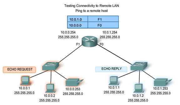
Ping Remote Host - Testing Connectivity to Remote LAN
You can also use ping to test the ability of the local IP host to communicate across an internetwork. The local host can ping an operational host of a remote network, as shown in the figure. If this ping is successful, you will have verified the operation of a large piece of the internetwork. It means that we have verified our host's communication on the local network, the operation of the router serving as our gateway, and all other routers that might be in the path between our network and the network of the remote host. Additionally, you have verified the same functionality of the remote host. If, for any reason, the remote host could not use its local network to communicate outside its network, then it would not have responded. Remember, many network administrators limit or prohibit the entry of ICMP datagrams into the corporate network. Therefore, the lack of a ping response could be due to security restrictions and not because of non-operational elements of the networks.
Traceroute (tracert) - Testing the Path
Ping is used to indicate the connectivity between two hosts. Traceroute (tracert) is a utility that allows us to observe the path between these hosts. The trace generates a list of hops that were successfully reached along the path. This list can provide us with important verification and troubleshooting information. If the data reaches the destination, then the trace lists the interface on every router in the path. If the data fails at some hop along the way, we have the address of the last router that responded to the trace. This is an indication of where the problem or security restrictions are.
Round Trip Time (RTT)
Using traceroute provides round trip time (RTT) for each hop along the path and indicates if a hop fails to respond. The round trip time (RTT) is the time a packet takes to reach the remote host and for the response from the host to return. An asterisk (*) is used to indicate a lost packet. This information can be used to locate a problematic router in the path. If we get high response times or data losses from a particular hop, this is an indication that the resources of the router or its connections may be stressed.
Time to Live (TTL)
Traceroute makes use of a function of the Time to Live (TTL) field in the Layer 3 header and ICMP Time Exceeded Message. The TTL field is used to limit the number of hops that a packet can cross. When a packet enters a router, the TTL field is decremented by 1. When the TTL reaches zero, a router will not forward the packet and the packet is dropped. In addition to dropping the packet, the router normally sends an ICMP Time Exceeded message addressed to the originating host. This ICMP message will contain the IP address of the router that responded. The first sequence of messages sent from traceroute will have a TTL field of one. This causes the TTL to time out the packet at the first router. This router then responds with an ICMP Message. Traceroute now has the address of the first hop.
Traceroute then progressively increments the TTL field (2, 3, 4...) for each sequence of messages. This provides the trace with the address of each hop as the packets timeout further down the path. The TTL field continues to be increased until the destination is reached or it is incremented to a predefined maximum. Once the final destination is reached, the host responds with either an ICMP Port Unreachable message or an ICMP Echo Reply message instead of the ICMP Time Exceeded message.
ICMPv4 - The Protocol Supporting Testing and Messaging
Although IPv4 is not a reliable protocol, it does provide for messages to be sent in the event of certain errors. These messages are sent using services of the Internet Control Messaging Protocol (ICMPv4). The purpose of these messages is to provide feedback about issues related to the processing of IP packets under certain conditions, not to make IP reliable. ICMP messages are not required and are often not allowed for security reasons. ICMP is the messaging protocol for the TCP/IP suite. ICMP provides control and error messages and is used by the ping and traceroute utilities. Although ICMP uses the basic support of IP as if it were a higher-level protocol ICMP, it is actually a separate Layer 3 of the TCP/IP suite. The types of ICMP messages - and the reasons why they are sent - are extensive.
ICMP messages that may be sent include:
-
Host confirmation
- Unreachable Destination or Service
- Time exceeded
- Route redirection
- Source quench
Host Confirmation
An ICMP Echo Message can be used to determine if a host is operational. The local host sends an ICMP Echo Request to a host. The host receiving the echo message replies with the ICMP Echo Reply, as shown in the figure. This use of the ICMP Echo messages is the basis of the ping utility.
Unreachable Destination or Service
The ICMP Destination Unreachable can used to notify a host that the destination or service is unreachable. When a host or gateway receives a packet that it cannot deliver, it may send an ICMP Destination Unreachable packet to the host originating the packet. The Destination Unreachable packet will contain codes that indicate why the packet could not be delivered.
Among the Destination Unreachable codes are:
0 = net unreachable
1 = host unreachable
2 = protocol unreachable
3 = port unreachable
Codes for net unreachable and host unreachable are responses from a router when it cannot forward a packet. If a router receives a packet for which it does not have a route, it may respond with an ICMP Destination Unreachable with a code = 0, indicating net unreachable. If a router receives a packet for which it has an attached route but is unable to deliver the packet to the host on the attached network, the router may respond with an ICMP Destination Unreachable with a code = 1, indicating that the network is known but the host is unreachable. The codes 2 and 3 (protocol unreachable and port unreachable) are used by an end host to indicate that the TCP segment or UDP datagram contained in a packet could not be delivered to the upper layer service. When the end host receives a packet with a Layer 4 PDU that is to be delivered to an unavailable service, the host may respond to the source host with an ICMP Destination Unreachable with a code = 2 or code = 3, indicating that the service is not available. The service may not be available because no daemon is running providing the service or because security on the host is not allowing access to the service.
Time Exceeded
An ICMP Time Exceeded message is used by a router to indicate that a packet cannot be forwarded because the TTL field of the packet has expired. If a router receives a packet and decrements the TTL field in the packet to zero, it discards the packet. The router may also send an ICMP Time Exceeded message to the source host to inform the host of the reason the packet was dropped.
Route Redirection
A router may use the ICMP Redirect Message to notify the hosts on a network that a better route is available for a particular destination. This message may only be used when the source host is on the same physical network as both gateways. If a router receives a packet for which it has a route and for which the next hop is attached to the same interface as the packet arrived, the router may send an ICMP Redirect Message to the source host. This message will inform the source host of the next hop contained in a route in the routing table.
Source Quench
The ICMP Source Quench message can be used to tell the source to temporarily stop sending packets. If a router does not have enough buffer space to receive incoming packets, a router will discard the packets. If the router has to do so, it may also send an ICMP Source Quench message to source hosts for every message that it discards. A destination host may also send a source quench message if datagrams arrive too fast to be processed. When a host receives an ICMP Source Quench message, it reports it to the Transport layer. The source host can then use the TCP flow control mechanisms to adjust the transmission.
Links:
RFC 792 http://www.ietf.org/rfc/rfc0792.txt?number=792
RFC 1122 http://www.ietf.org/rfc/rfc1122.txt?number=1122
RFC 2003 http://www.ietf.org/rfc/rfc2003.txt?number=2003